Add: Room 501, No.6, West 4th Alley, XingWei Village, FuYong Town, BaoAn District, Shenzhen, China
E-mail: luke@jaydagate.com
Wechat: Lukerong2013
Whatsapp: +86-13548106515
Mobile: +86-13548106515
Skype: jaydagates@outlook.com
Flap barriers, also referred to as flap barrier turnstiles or flap turnstile gates, are efficient crowd access control solutions created for applications requiring medium levels of security and ultra-high speeds of access. They are used to control pedestrians entering or leaving monitored, secured areas. To spread their wings and let go of a single passage in the desired direction, the flap barrier systems need a valid credential. The built-in sensors detect any illegal passage attempts and sound an alarm if an unauthorized user tries to enter without permission or tailgate on a valid entry. The flap turnstile systems immediately close the passage after a person passes through or after the predetermined amount of time; the passing time can be programmed to meet specific needs. In the event of a power outage or fire alarm input, such interior automatic turnstiles will be opened automatically to provide a clear exit passageway.
To ensure that only one person enters with each authorized credential at once, the optical flap turnstiles are equipped with several infrared sensors. Any unauthorized intrusions or tailgating attempts will be rejected and result in an audible alert. Contrarily, they are more straightforward and integrate any kind of access control system to support multiple verification techniques like face recognition, RFID reading, and QR code reading. Additionally, motorized retractable wings for fast, dependable, bi-directional operation with minimal noise and energy consumption are available with them.
Access control flap turnstiles adopt a streamlined design with a more modern aesthetic to meet the latest architectural trends, widely used for corporate lobbies, office buildings, data centers, government facilities, and stadiums. As quick throughput is available with them, such automatic turnstile gates are often implemented in subways and other public transportation terminals.
As a reputable manufacturer and supplier of flap turnstiles with strong manufacturing and R&D capabilities, our company offers a range of flap gate optical turnstiles with various designs and prices. We also regularly introduce new products for customers around the world, and we can customize flap turnstile gates to meet specific client needs. Please get in touch with us for prices and additional information.


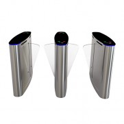
 Flap Barrier Gate Turnstile JDYZ-30
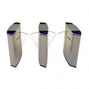
 Flap Gate Optical Turnstile JDYZ-29
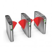
 Access Control Flap Turnstile JDYZ-28
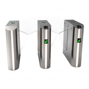
 Flap Barrier Turnstile JDYZ-27
 Flap Turnstile Gate JDYZ-23
 Flap Barrier Gate JDYZ-9
 Flap Barrier System JDYZ-15
 Optical Flap Turnstile JDYZ-19
 Flap Turnstile Access Control System JDYZ-2