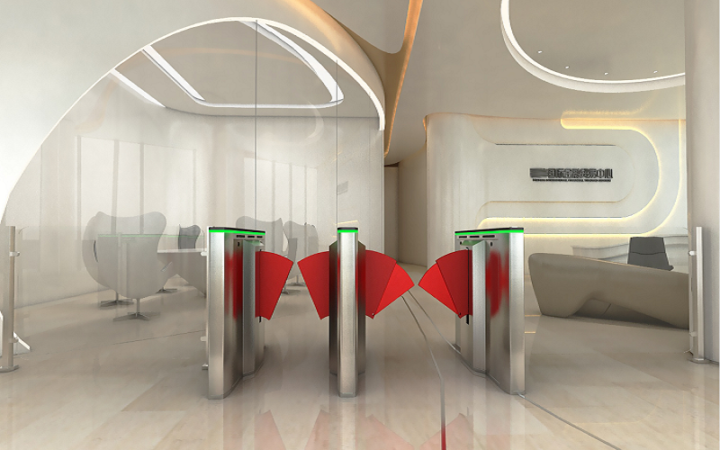
The overview of a flap turnstile
It relates to a flap turnstile for access control of a secured area according to the preamble of claim 1 and a personal barrier with such a turnstile gate.
A flap turnstile is used for secured areas to control the access of pedestrians, but this access must be controlled. One function of the barrier optical turnstile is to prevent people who want to get into the secured and usually cordoned off or regulated area. This function is often in the foreground at concerts and sporting events as well as when leaving particularly protected areas such as the gate area of an airport. Another function of a flap barrier turnstile is important in secured areas that can only be entered with specific authorization. Such a specific authorization can be an admission ticket, a membership card, a passport or a ticket for public transport such as subways, S-Bahn, other railways or air taxis. However, the specific authorization can also lie in the presence of biometric data with which a person authorized to access can be clearly identified.
In the case of flap turnstiles through which a large number of people are to be moved through in a controlled manner in as short a time as possible, such as in train stations, metro stations and the like (particularly in the “Automatic Fare Collection” area), it has proven useful to use glass turnstile doors with locking devices, the blocking element of which is as pivoting flap is formed. This can be pivoted about a horizontally oriented pivot axis into a passage next to the locking device or into a corridor between two locking devices to assume a locking position, and pivoted out of this passage to assume a release position. In the release position, the flap is typically housed in a barrier housing.
Such locking elements designed as flaps can be moved particularly quickly between the locking position and the release position, with a typical running time of 0.3 seconds to 0.6 seconds. This is because the air resistance during the pivoting movement is very low and does not increase with the air resistance compare, which acts, for example, on doors that are pivoted about a vertical axis; At the same time, by pivoting the flap into the lock housing and largely or completely incorporating it into the lock housing, the risk of accidents caused by flap movements is minimized.
As a rule, two glass wing optical turnstiles of this type form a corridor between them, through which people can only walk one behind the other. The locking elements of the two optical flap barriers are both pivoted into this corridor at the same time to assume their locking position, and they lie opposite each other to form two halves of a barrier form that blocks the passage for people.
In the event of a panic in the secured area, which can result from a fire, a terrorist attack or even just a power failure, for safety reasons it must be ensured that the locking elements of all physical barriers are moved into the release position in order to open escape routes. For safety reasons, it is not tolerated that in such an emergency, especially if the power supply fails, the locking elements have to be pivoted into the release position by hand, because there is a risk that this will become impossible due to people pushing behind.
Flap turnstile gates of the present type include a base frame, a locking element which is pivotally mounted on the base frame about a substantially horizontally oriented pivot axis and which can be moved back and forth between a release position and a locking position, and a drive device for the locking element which is attached to the base frame and is connected to the locking element.
For the safety reasons described above, the locking element of an access turnstile of the present type is provided with a return device in order to move it into the release position in the event of a failure or malfunction of the drive device, or even when an emergency stop function is triggered. Optimally, the locking element is also held in the release position by the return device as long as the drive device is not functioning.
In the prior art, return devices are known which move the locking element into the release position with the aid of the drive device, in particular in the event of a power failure, a power storage element, for example a capacitor, provides the energy supply for the drive device, which usually consists of an electric motor and possibly a gearbox exists, at least supplied with electrical energy until the locking element has been pivoted into the release position. However, if the locking element is loaded by people pushing towards it, for example, the drive device requires longer or more electrical energy to bring the locking element into the release position. This case is then either not covered by the safety concept, or it must be taken into account, which may require cost-intensive additional units.
Another approach for the return device is to mechanically connect the locking element to a return spring. In order to pivot the locking element into the locking position, the drive device must then work against a spring preload; However, this is not a problem if the forces are balanced accordingly. What is more problematic is that such a return spring follows every pivoting movement of the blocking element due to the rigid mechanical coupling and is thereby tensioned and relaxed in each case. However, flap gate turnstiles of the present type typically carry out tens of thousands of pivoting movements every day in order to release and block access and to isolate people. Over the entire lifespan of a security turnstile gate, there are many millions of opening and closing cycles in which the return spring is then relaxed and tensioned.
It can therefore happen that such a return spring breaks over time. A broken return spring represents a significant safety risk, as the locking element is no longer automatically pivoted into the release position in an emergency, but blocks a possible escape route. What is particularly problematic is that this security risk is not even recognizable in daily operations.
It is therefore based on the object of proposing a locking device of the present type and a personal lock with such a flap turnstile barrier, the return device of which is reliably operational over the entire service life of the flap turnstile barrier gate and yet is structurally inexpensive.
This task is solved by a fla turnstile with the features of claim 1 and by a personal barrier with the features of claim 8.
Preferred embodiments of the flap barrier optical turnstile can be found in claims 2 to 7; An advantageous development of the flap type turnstile is set out in claim 9.
A flap turnstile gate for access control of a secured area, with a base frame, with a locking element movable between a release position and a locking position, which is pivotally mounted on the base frame about a substantially horizontally oriented pivot axis, and with a drive device attached to the base frame for the Locking element, wherein the locking element is connected to a return device in order to move it into the release position and / or hold it there in the event of a failure or malfunction of the drive device, or when an emergency stop function is triggered, is therefore improved according to the invention with regard to the return device : This consists of a return weight that is dimensioned and mechanically connected to the locking element in a positive or non-positive manner in such a way that it moves the locking element into the release position and/or holds it there when the drive device is switched off due to the weight of the return weight.
The flapl barrier turnstile for access control of a secured area contains the locking device, which is housed in a barrier housing, the barrier housing having an opening for the locking element.
A return weight does not require an energy supply, as it works by means of gravity, nor does it pose the risk of fatigue failure. After switching off the drive device, the locking element, which is mechanically connected to the return weight, is moved reliably and independently into the release position and held there. The drive device is switched off automatically in the event of a failure or malfunction, in particular if the power supply fails. When an emergency stop function is triggered, the drive device is also switched off or the power transmission is separated, so that in all these cases the weight of the return weight ensures a reliable and ensures complete pivoting of the locking element into the release position. At the same time, this design of a return device according to the invention is structurally very simple to implement and inexpensive.
Further advantages of the entrance solution are related to the other disadvantages of the prior art with a hollow return spring: the spring force of a hollow return spring reduces over time due to settling phenomena, which is why the return spring has to be dimensioned larger than would actually be necessary for the return function. It must be ensured that there is still enough spring force for the return function even after tens of millions of movement cycles. The usual tolerances of typically +/- 5% in the spring force of identical return springs also force a safety premium and thus, on average, also lead to the return spring being oversized.
A hollow return weight, on the other hand, can be manufactured much more precisely with regard to its weight, and there is no fear that the weight will decrease over time. Thus, the weight of the hollow return weight can be adapted much more precisely to the force actually required for hollowing back the locking element, which puts less strain on the drive motor and advantageously reduces the energy requirement for the movement cycles and for holding the locking element in the locking position.
Advantageously, the security solution also eliminates the generation of noise that is commonly observed in the prior art with return springs. Such spring noises are caused by stipslick effects on the spring suspensions. These cause the return springs to vibrate, which causes noise. In addition, with return springs there are squeaking noises and wear on the spring holders, which can only be avoided with complex and expensive ball bearings; These problems also disappear with the hollow return weight according to the invention.
The drive device of the flap gate barrier is preferably connected to the locking element via a lever arrangement or a linkage and the return weight is integrated into the lever arrangement or the linkage. This enables a particularly simple mechanical coupling of the return weight to the locking element, since the connection of the linkage or the lever arrangement to the locking element already exists and a separation or decoupling of the drive device from the lever arrangement or from the linkage does not affect the return device in any way.
It is particularly preferred here if at least part of the lever arrangement or the linkage is designed as a return weight, i.e. the return weight is not added as a separate component. Rather, in particular a lever or a linkage part is dimensioned such that, when the levers or the linkage are arranged accordingly, it acts as a return weight and reliably pulls the locking element into the release position when the drive device is switched off.
The locking element is also preferably designed as a plate-shaped flap, optionally with additional struts, stiffeners, holding rails and the like. This flap preferably essentially has the shape of a circular sector, a circular ring sector or a trapezoid, the wider side of this shape preferably forming the upper region and the narrower side forming the lower region of the plate-shaped flap. In this case, it is useful if the locking element is pivotally mounted on the base frame in the lower area of the flap or below it and the wider area of the flap is used to pivot into the locking position.
The locking element can also be a plate-shaped telescopic flap, which strictly speaking consists of at least two flaps, which preferably have essentially the shape of a circular sector, a circular ring sector or a trapezoid and are telescopically inserted into one another in order to fan out during a pivoting movement into the locking position and to increase the area of the locking element accordingly, and conversely to reduce the area when the locking element is pivoted back into the release position. This allows a passageway of greater width to be blocked without having to make the barrier housing wider to accommodate the flap.
If the drive device of the flap barrier gate turnstile is essentially formed by an electric motor with or without a gear, it is advantageous if the electrical and electronic components for the operation and control of the electric motor are attached to the base frame.
Finally, the flap turnstile barrier comprises two barrier housings, which form a corridor between them and in each of which a barrier device is housed. The locking elements of the two turnstile housings can be pivoted synchronously into and out of the corridor from both sides in order to assume the locking position or the release position. As a result, the blocking elements only have to be pivoted so far that they block off almost half of the width of the corridor. This enables particularly short running times for locking and unlocking the corridor. If the locking elements are flaps, with typical dimensions of the lock housing it is usually sufficient to swing the flaps out of the lock housing by 20 to 30 degrees, around a standard corridor of typically 500mm to 600mm wide, for telescopic flaps Typically up to 900mm wide.
Exemplary embodiments of a retractable flap barrier are described and explained in more detail below with reference to the accompanying drawings.
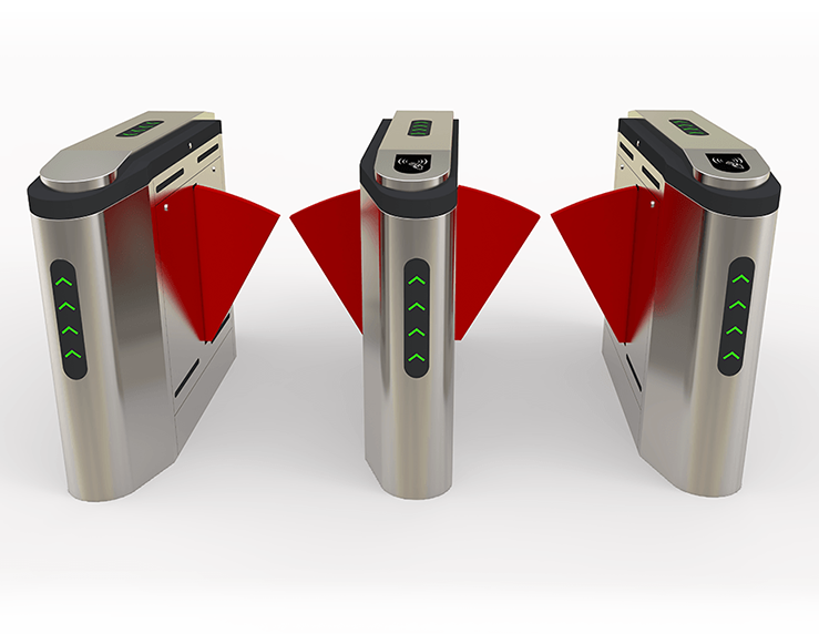
Figure 1 is an isometric representation of a flap turnstile designed according to the invention with a locking element in the locking position;
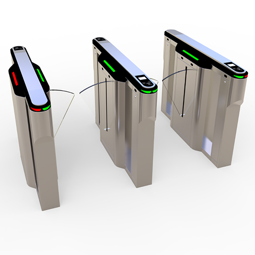
Figure 2 is an isometric representation of two flap turnstiles designed, which form a corridor.
Figure 1 shows an exemplary embodiment of a flap turnstile 14 designed with a base frame 1 and a locking element 2, which is designed here as a plate-shaped flap 3, which essentially has the shape of a circular ring sector, with a narrow area at the bottom and a wide area at the top. A holding profile 4 and a pivot bearing 5 complete the locking element 2, which can be pivoted about a pivot axis 6 running essentially horizontally through the pivot bearing 5 between a release position (not shown) and a locking position, the pivot bearing 5 being seated in the base frame 1.
As can be seen from Figure 1, an electric motor 7 is attached to the base frame 1 as the main component of a drive device 8 on the back of the base frame 1. A motor shaft 9 of the electric motor 7 is passed through the base frame 1 and connected to a lever arrangement 10, which mechanically connects the motor shaft 9 of the drive device 8 to the holding profile 4 of the locking element 2 and ensures that a movement of the electric motor 7 is applied to the locking element 2 is transmitted that when the electric motor 7 rotates by, for example, 180 degrees, the locking element 2 is pivoted, for example, by 25 degrees about the pivot axis 6.
The special feature of this exemplary embodiment is that part of the lever arrangement 10 is designed as a return weight and the lever arrangement 10 runs in such a way that the weight of the return weight 11 pulls the locking element 2 into its release position when the electric motor 7 is switched off or when the power flow is separated. This means that the emergency opening of the locking device 14 occurs automatically and necessarily purely due to the gravity of the return weight 11, the mass of which is dimensioned accordingly.
The drive device 8 of the present example can also be a low-energy drive, in which the lever arrangement 10 is not actuated by rotating the electric motor 7 by the typical 180 degrees of angle, but by only approximately 40 degrees of angle. This is advantageous because, for safety reasons, it is the norm for personal locks that the locking element 2 must not exert a force greater than 67N on its front edge when it hits an obstacle, for example a person standing in the movement range of the locking element 2. Thus, the lever arrangement 10 does not have to be moved too close to a dead center position in order to bring the locking element 2 into the locking position, and accordingly the motor torque of the electric motor 7 does not have to be reduced so much due to an increasing gear reduction by the lever arrangement 10 that it is necessary for that Acceleration and normal operation of the locking device would no longer be sufficient if the engine torque is not regulated in a complex position-dependent manner.
Further components for the energy supply of the electric motor 7 and for the electronic control of the same, such as connection terminals, control unit, power supply, relay, etc. (not shown) can be attached directly to the base frame 1 or can also be arranged on a separate mounting plate, which in turn is fixed to the base frame 1 can be.
In Figure 2, automatic flap barrier 13, 13 ‘with locking devices 14, 14′ designed according to the invention according to Figure 1 are shown. The locking elements 2, 2′ of the locking devices 14, 14′ act towards a corridor 12 in order to lock it for people in the locking position and to release it for people in the release position (not shown). The two personal barriers 13, 13′, which each consist of a locking device 14, 14′, as shown in Figure 1, and a barrier housing 15, 15′ in which the locking devices 14, 14’ are accommodated, form between them Corridor 12, the two barrier housings 15, 15 ‘forming the side walls of the corridor 12 and in particular ensuring that the people guided through the corridor 12 are separated.
The barrier housings 15, 15 ‘can, for example, be provided on their upper front edge, which can be seen in Figure 2, with an authorization module (not shown) for checking a specific authorization to pass through the corridor 12.
The return device designed can, as is clear from the exemplary embodiment shown in the figures, be implemented in a very simple construction, although it reliably ensures at any time and over the entire service life of the locking device 14 that the locking device 14 moves the locking element 2 into its release position in an emergency and thereby opens up possible escape routes. In any case, the return function cannot be lost undetected, as is the case if a return spring breaks.
List of symbols for reference
1. Base frame
2. Locking element
3. Flap
4. Holding profile
5. Pivot bearings
6. Pivot axis
7. Electric motor
8. Drive device
9. Motor shaft
10. Lever arrangement
11. Return weight
12. Corridor
13. Person blocking
14. Locking device
15. Barrier housing
Claims
1. Flap turnstile (14) for a pedestrian barrier 15) for access control of a secured area, with a base frame (1), with a locking element (2) movable between a release position and a locking position, which is on the base frame (1) by a substantially horizontal oriented pivot axis (6) is pivotally mounted, and with a drive device (8) attached to the base frame (1) for the locking element (2), the locking element (2) being connected to a return device in order to move the locking element (2) in the event of a failure or a malfunction of the drive device (8) or when an emergency stop function is triggered to move into the release position and/or to hold it there, characterized in that the return device consists of a return weight (11) which is dimensioned and shaped in this way is non-positively mechanically connected to the locking element (2) so that it moves the locking element (2) into the release position and/or holds it there when the drive device (8) is switched off due to the weight of the return weight (11).
2. Flap turnstile gate (14) according to claim 1, characterized in that the drive device (8) is connected to the locking element (2) via a lever arrangement (10) or a linkage, and that the return weight (11) is inserted into the lever arrangement (10). or the linkage is integrated.
3. Flap gate turnstile (14) according to claim 2, characterized in that at least part of the lever arrangement (10) or the linkage is designed as a return weight (11).
4. Flap barrier turnstile (14) according to at least one of claims 1 to 3, characterized in that the locking element (2) contains a plate-shaped flap (3), which preferably has essentially the shape of a circular sector, circular ring sector or trapezoid.
5. Flap optical turnstile (14) according to claim 4, characterized in that the locking element (2) is pivotally mounted on the base frame (1) in the lower region of the flap (3) or below it.
6. Anti-trailing flap turnstile gate (14) according to at least one of claims 1 to 5, characterized in that the drive device (8) contains an electric motor (7).
7. Automated flap barrier turnstile (14) according to claim 6, characterized in that electrical and electronic components for the operation and control of the electric motor (7) are attached to the base frame (1).
8. Security flap turnstile barrier (13) for access control of a secured area, with a barrier housing (15), a locking device (14) accommodated therein according to at least one of claims 1 to 7 and an opening for the locking element (2).
9. Flap turnstile system (13) according to claim 8, with two barrier housings (15, 15′), which form a corridor (12) between them, and a locking device (14, 14′) accommodated in each barrier housing (15, 15′). , whose locking elements (2) can be pivoted essentially synchronously into the corridor (12) and out of it from both sides in order to assume the locking position or the release position.


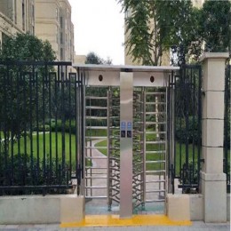


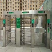
 Double Lane Full Height Turnstile Gate for Residential Area
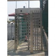
 Dual Lane Tandem Full Height Turnstile Gate for Industry Park
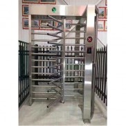 Single Full Height Security Turnstile for Office Buildings
 Motorised Double Full-Height Turnstile for Office Buildings
Please leave a message if you are interested in this model