The controlling method to operate a turnstile system
The general description of the controlling method to operate a turnstile system
It relates to a control method for operating a turnstile system used to control the passage of people, with a locking element that can be rotated about a fixed pivot axis, which has locking means that extend from the pivot axis, including preferably equal angles, which can be moved from their normal operating positions to non-use positions and can also be actuated one after the other as a result of the locking element rotating about its pivot axis from a rotational position that blocks a passage of people to a rotational position that releases the passage of people, whereby when a locking means is moved from its locking position to a position that releases the passage of people, the locking means that follows in the direction of rotation is moved to the locking position, and when an event that disrupts normal operation occurs, such as a power failure, at least the locking means in the locking position is moved from a position that blocks the passage of people to a non-use position that allows the uncontrolled passage of people. movable and this locking device can be returned to its normal operating position after the aforementioned event has ceased and can be releasably locked in this operating position.
A turnstile system for controlling the passage of people, with a pedestrian turnstile that can be rotated around an axis of rotation inclined at 45° to a vertical as a blocking element. The exterior turnstile has three blocking arms that extend trigonally from a bearing plate and that can be moved one after the other into an essentially horizontal blocking position or positions that allow people to pass when the turnstile is rotated around its bearing axis. These blocking arms normally protrude from the bearing plate at a predetermined angle to the axis of rotation, but are hinged to the latter in a foldable manner and are held in their normal operating positions by means of releasable locking mechanisms.
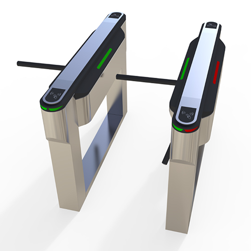
The turnstile entry systems have proven to be an excellent means of controlling the passage of people, in particular because, for example, when the turnstile barrier arms are held in their normal operating positions, in which they move one after the other into a blocking position that blocks a passage for people by rotating the blocking element, an electromagnetic latch causes the barrier arms in the blocking position to swing under the effect of gravity into the respective opening position in the event of a power failure or intentional power cut. In the event of operational disruptions, it is therefore ensured that employees are not locked in in an area secured by such turnstile systems in the event of danger, for example, but that such an area can be essentially closed off via the turnstile access control system, which can then be used as an escape route.
What is unsatisfactory, however, is that after an event that causes the locking elements to fold down, such as a power failure, the half height turnstiles have to be re-set in a complicated and time-consuming way, as the locking arms, which had previously been folded down from their locking positions when the disruptive event occurred, have to be returned to their normal operating positions by hand. This is particularly annoying if, for example, a large company site is secured using a large number of such access control turnstile systems.
A very similar security turnstile system in which three locking arms are also arranged on a bearing disk that rotates around an axis of rotation that is inclined to the vertical. As a result of the rotation of the bearing disk, these locking arms move one after the other into a horizontal locking position and in this position block a passage for people. In this security solutions turnstile, the locking arms can be folded down after the locking mechanisms that hold them in their normal positions have been released, with the result that when such an event occurs, the locking arm that is in the locking position at any given time pivots under the effect of gravity into a position that allows the passage in question to be opened.
It is also unsatisfactory with this previously known security system turnstile that when the event causing the locking arm in the locking position to fold down ceases, i.e. when normal operation resumes, this locking arm has to be folded back manually into its intended position.
Finally, a turnstile system, in which locking wings arranged radially around a guide column with a vertical axis of rotation are provided as a locking device and in order to create escape routes in the event of danger, at least two locking wings can be pivoted about axes parallel to the barrier gate turnstile axis of rotation or folded down from their locking positions. Folding down the locking wings also allows uncontrolled passage of people in this turnstile system.
While both of the access control turnstile systems discussed above have locking arms that protrude into a pedestrian passage in the locking position, the latter automatically fold down into a position that allows the pedestrian passage depending on a defined event, the turnstile entrance system discussed last requires the folding locking wings to be pivoted about their pivot axes that run parallel to the axis of rotation of the locking element, and after the aforementioned event has ceased, the folded locking wings must be folded back manually into their intended normal positions. This is cumbersome and time-consuming.
It is therefore based on the object of creating a control method in which a locking device of a turnstile system that has been moved from its locking position to a non-use position is forcibly returned to its intended normal position without manual operation. A control method must therefore be specified that enables the turnstile system to automatically return to its normal, operational state.
This problem is solved in that in a security turnstile entrance system specified in the preamble of patent claim 1 the locking element is connected to an electric stepping motor and that after the event that triggers the mobility of at least the locking means in the locking position in its non-use position has ceased, restoring forces that, in relation to the articulation axis of the locking element, cause a locking means in a non-use position to be returned to its normal operating position are brought to act on the locking means in the non-use position by stepping the locking means forward by at least one step.
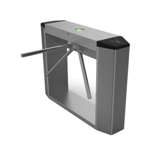
It is therefore characteristic of the control method, after the elimination of an event that disrupts normal operation and has caused the movement of at least the locking means in the locking position into a non-use position, restoring forces are applied to a locking means in its non-use position and that this locking means is thereby returned to its normal operating position, thus setting up the turnstile system for the resumption of normal operation.
For this purpose, the locking element of the anti tailgating turnstile access control system is connected to an electric stepping motor which, after the event that triggers the mobility of at least the locking means in the locking position in its non-use position has ceased, causes the restoring forces that cause the said locking means to return to its normal operating position to act on the locking means by stepping the locking means forward by at least one step.
This development therefore involves the restoring forces which cause the resetting of a locking means moved from its normal operating position to a non-use position being brought to bear on the locking means in the non-use position as a function of the advance of the locking element.
In a turnstile system with a locking element’s axis of rotation inclined relative to a horizontal and locking arms as locking means that are at least approximately horizontal in their locking positions and that fold down under the effect of gravity when an event occurs that triggers the mobility of the locking means in the locking position into a non-use position, according to another development of the invention, the resetting of a folded-down arm can be achieved when, when the locking element is advanced, the articulation axis of this locking means on the locking element runs through a lower region of its orbit when the locking element rotates about its axis of rotation. In this rotation region of the locking means, the weight forces acting on its center of gravity act in the sense of a resetting of the locking means to a position corresponding to normal operation.
A locking device that has been folded down into a non-use position is returned to its normal operating position with particularly high reliability if, in a electronic pass control system with three locking arms arranged approximately trigonally to the axis of the locking element, the reset is carried out when the locking element is advanced by at least two consecutive switching steps, i.e. the locking arm in the folded down position with its articulation point on the locking element runs through the lower culmination area of its orbit.
Finally, another very important embodiment of the control method provides that the locking means moved in their non-use positions are returned to their normal positions after the event that triggered this mobility has ceased when the locking element is switched on as a result of the centrifugal forces that occur and act on these locking means.
While in the two further developments discussed above, the resetting of a locking device from its folded-down non-use position to the normal operating position was carried out when the locking element rotated under the effect of gravity, in the last development discussed, the restoring forces are applied to the folded-down locking device in the form of centrifugal forces. These centrifugal forces always act at the center of gravity of the folded-down locking device and are directed radially to the axis of rotation, but regularly have components falling in a direction perpendicular to the folding axis, which have a restoring effect and in the sense of re-establishing the device in the normal operating positions.

The detailed description of the controlling method to operate a turnstile system
An embodiment will be explained below with reference to the accompanying drawing. Schematic views show:
Fig 1: looking in the direction of passage, a turnstile system with a three-barrier arm that can be rotated around an axis of rotation inclined at approximately 45° to a horizontal axis, one of whose barrier arms is in a horizontal blocking position that blocks the passage of people,
Fig 2: the turnstile system in a side view looking in the direction of arrow II in Fig.1,
Fig 3: the turnstile system in a view as in the barrier arm blocking the passage of people in a non-use position folded down and allowing the passage,
Fig 4: a side view of the turnstile system with the barrier arm folded down and the direction of view according to arrow IV in Fig.3 and
Fig 5: in an enlarged detail view from Fig.1 the mounting of a locking arm that can be folded down from the normal position shown on a turntable, which in turn can be rotated about the inclined axis of rotation and driven by a motor.


In the turnstile system 10 shown in the drawing, a drive unit 12 with a turnstile 13 is mounted on a column 11, which has three locking arms 14, each offset by 120° from one another, and is mounted on the drive unit 12 so as to be rotatable about an axis of rotation 15 inclined by approximately 45° to an imaginary horizontal. The locking arms are in turn hinged to a bearing plate 16 about articulation axes running at right angles to the axis of rotation of the turnstile, from their normal positions shown in particular in Fig.1 to non-use positions, which in turn is in direct drive connection with an advance motor (not shown) housed in the drive unit 12 and can therefore be rotated about the aforementioned axis of rotation 15 during advancement. The locking arms 14 extend trigonally from the bearing plate 16, specifically on the casing of an imaginary region extending in the direction of the bearing.
In normal operation, one of the three locking arms 14 is in a horizontal locking position extending into a pedestrian passage, while the other two locking arms 14 are pivoted out of the passage into positions pointing diagonally downwards, as shown in particular in Figs.1 and 3. When a person enters the outdoor turnstile access control system 10, the locking arm in the locking position is moved out of its locking position as a result of being triggered by this person by means of the indexing motor by rotating the bearing plate 16 and thus the turnstile 13, thus allowing the pedestrian passage. At the same time, the locking arm 14 following in the direction of rotation comes into a locking position blocking the passage behind a person passing through.
In the crowd control turnstile system 10 shown, with locking arms 14 arranged offset by 120° from one another, one rotation cycle of the turnstile 13 corresponds to a rotation of 120° and in normal operation one locking arm is in a locking position that blocks the passage of people. In this case, locking arms 14, which can be folded down like plates 16 about a pivot axis, are releasably locked in the normal operating positions shown in particular in Fig.1 and are held in these locking positions by electromagnets, which is explained in more detail below in connection with Fig.5. If, due to a power cut or power failure, the electromagnetic mounting of the locking arms in the above-mentioned locking positions is no longer possible, the locking arm 14, which is in its essentially horizontal locking position, folds down under the effect of gravity from this locking position, which corresponds to the normal operating position, into a non-use position that releases the assigned pedestrian passage, as shown in Fig. 3. Since, given the representation of the turnstile 13, the other two locking arms also release the passage, uncontrolled pedestrian passage is possible after the locking arm, which was originally in the locking position, has been folded down.
After the event which triggers the folding down of the respective locking arm in the locking position has ceased, the turnstile system 10 is reset to its normal operating position by rotating about the axis of rotation 15 in such a way that the locking arm 14 which has been folded down in the non-use position pivots back into its normal operating position under the effect of gravity about its articulation axis on the bearing plate 16 and locks there. This pivoting of a folded down locking arm back into its normal operating position is achieved in a particularly safe manner if, in the case of a waist-high turnstile with three locking arms which are each offset by 120°, after the event which triggers the folding down of a locking arm has ceased, the turnstile becomes the turnstile so that the articulation axis of the locking arm 14 which is to be returned from its non-use position to the normal use position passes through the lower culmination point of its orbit on the bearing plate 16.
In Fig.5, with the other locking arms omitted, the articulation of a locking arm 14 on the bearing plate 16 of the drive unit 12, which can be folded down from the shown operating position into a non-use position, is illustrated. This articulation is provided by bearing pins 20 running at right angles to the axis of rotation 15 of the turnstile 13. These bearing pins are accommodated on the bearing plate 16 in a manner not of further interest here, which in turn is fastened in a rotationally fixed manner to a block body 21 that is in drive connection with the drive shaft of the indexing motor. A bearing tongue 22 arranged at the end of the respective locking arm 14 is pivotally accommodated on each of these bearing pins. On the side of the bearing pin 20 facing away from the actual locking arm, the respective bearing tongue has a locking shoulder 23, which is engaged behind by a locking nose 24 of a rotary latch 25. The steering axis of the respective locking arm is pivotally mounted on the bearing pin 26 arranged on the bearing plate 16 in a recess of the block body 21 which is connected in a rotationally fixed manner to the bearing plate 16, namely against the action of a return spring 27.
At its end facing away from the respective bearing pin, the associated rotary latch 25 has a nose 28 directed radially outwards, which is engaged by a projection 29 of a slide 30 directed towards the axis of rotation. This slide is held in its position shown in Fig.5 by an electromagnet 31.
In the event of an event leading to a malfunction, the current supply to the electromagnet 31 is interrupted, with the result that a return spring 32 acting on the slide 30 pulls the slide from the holding position shown in Fig. 5 and in the process pivots the rotary latch 25 about the pivot axis formed by the bearing pin 26 on the block body 21. As a result, the locking nose 24 of the rotary latch comes out of engagement with the locking shoulder 23 of the bearing tongue 22 and then the locking arm 14 pivots under the effect of its own weight from its horizontal locking position into a vertical position. The two locking arms not shown in Fig. 5 are mounted in an identical manner to the locking arm shown and are held in their normal operating positions or can be unlocked from these.

Claims
1. Controlling method for the operation of a secure entrance turnstile installation serving to check the passage of persons. With a barrier element which is rotatable about a hinge axis fast with the installation and which comprises barrier means which extend forth from the hinged axis at preferably equal angles and which into settings of non-use and for the remainder are actuable one after the other out of a rotary setting which blocks the passage of a person into one freeing that passage in consequence of rotation of the barrier element about its hinge axis, wherein – on each stepping-on of a barrier means out of its barrier position into a setting freeing the passage of a person – the barrier means following in the direction person – the barrier means following in the direction – on the occurrence of an event, such as current failure the occurrence of an event, disturbing the normal operation – at least the barrier means standing in the barrier position is moved out of its position barring the passage of persons into a setting of non-use enabling the unchecked passage of persons and this barrier means is resettable into its normal operative setting after the disappearance of the mentioned event as well as releasably detentable in this operative setting, characterised thereby, that the barrier element stands in driving connection with an electrical stepping motor and that – after disappearance of the event initiating the movability of at least the barrier means, which stands in the barrier position, into its setting of non-use – restoring forces, which cause setting of non-use – restoring forces, which cause of non-use into its normal operative setting with respect to the hinge axis of the barrier element, are brought into effect on the barrier means standing in the setting of non-use by stepping the barrier means forth through at least one forward step.
2. Controlling method according to claim 1, characterised thereby, that in the case ofa entrance control turnstile installation with a rotational axis Of the barrier element inclined to the horizontal and standing at least nearly horizontally in its blocking positions as well as on the occurrence of the event causing the movability of the barrier means into a setting of none use under gravitational effect of tilted-away barrier arms as barrier means, the resetting of a tilted-away barrier means takes place under gravitational effect when the hinge axis of this barrier means runs through a lower region of its circulatory path at the barrier element on the rotation of the barrier element about its axis of rotation.
3. Controlling method according to claim 2, characterised thereby, that in the case ofa react-turnstile installation with three barrier arms arranged about trigonally relative to the rotational axis of the barrier element, the resetting of a barrier arm, which was tilted away into a setting of non-use, into its normal setting is carried out on the switching of the barrier element forward through two successive switching steps.
4. Controlling method according to claim 1, charactersettings of non-use are, after the disappearance of the event initiating their movability into the settings of non-use, reset into their normal settings during the stepping-on of the barrier element and in consequence of inertia forces arising in that case and acting in those barrier turnstile means.
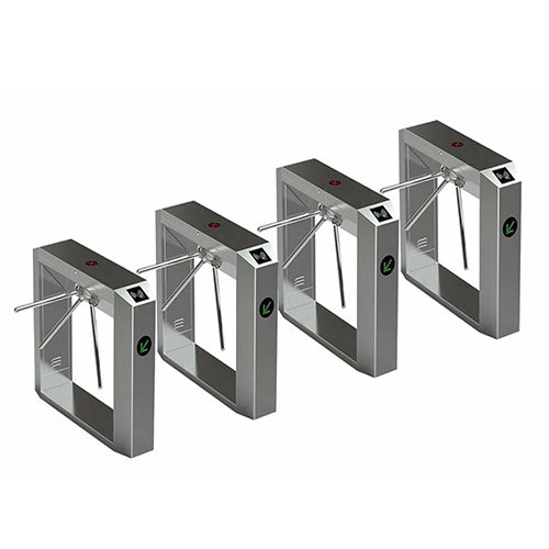
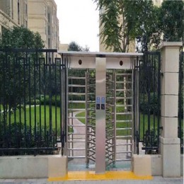
 Double Lane Full Height Turnstile Gate for Residential Area
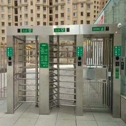
 Dual Lane Tandem Full Height Turnstile Gate for Industry Park
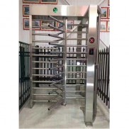 Single Full Height Security Turnstile for Office Buildings
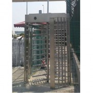 Motorised Double Full-Height Turnstile for Office Buildings




Please leave a message if you are interested in this model