Add: Room 501, No.6, West 4th Alley, XingWei Village, FuYong Town, BaoAn District, Shenzhen, China
E-mail: luke@jaydagate.com
Wechat: Lukerong2013
Whatsapp: +86-13548106515
Mobile: +86-13548106515
Skype: jaydagates@outlook.com
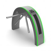
Tripod turnstiles, also referred to as waist height turnstiles or tripod turnstile security gates, are the conventional and affordable variety of pedestrian turnstile gates that restrict access to one person at a time with rotating tripod barrier arms and provide pedestrians with a simple and comfortable entry into a secured area.
The tripod turnstile gates slow down traffic and, when necessary, enable closer monitoring of the ingress security guards. Such security turnstiles unlock when a valid credential signal is received; all it takes is a light touch of the horizontal boom to release the passage and relock in the home position after passage. The convenience and security of pedestrians are ensured by their easy integration with access control and visitor management systems, and their automatic release following identity verification. The horizontal turnstile arm lowers in an emergency, allowing customers who are leaving free passage.
Depending on the actual needs, these tripod turnstile entrance control can be set up to permit access either one way or both ways. Additionally, the tripod barrier turnstiles serve as an efficient crowd control solution for a range of applications, including stadiums, amusement parks, office buildings, and cafeterias in addition to athletic facilities, schools, and cafeterias.
As a reputable turnstile manufacturer and supplier with strong manufacturing and R & D capabilities, our company offers a range of tripod turnstile access control systems with various designs and prices. We also continuously introduce new products for customers around the world each year, and we can also customize turnstile gates to meet specific client needs. Please get in touch with us if you need additional information


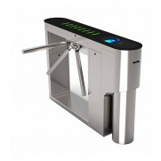
 Automatic Tripod Gate System JDGD-30
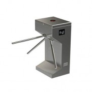
 Aesthetic Waist High Turnstile Gate JDGD-27
 Access Control Tripod Turnstile JDGD-22
 Tripod Security Gate JDGD-20
 Automatic Tripod Barrier Turnstile JDGD-21A
 Vertical Tripod Barrier Gate JDGD-1
 Tripod Turnstile Gate JDGD-17