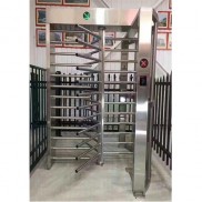
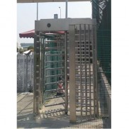
Full body turnstile for controlling the rotation
A full body turnstile controlles the rotary movement of the rotating star by means of a drive motor which is coupled to the rotary axis of the rotating star.
It is known to install automatic pedestrian gates at the entrance to sports facilities such as ski lifts, sports halls, swimming pools, event centres, shopping centres etc., which can be controlled using coins, value cards, tokens etc. in order to allow access to the facilities etc. These modern pedestrian gates are known as entrance security turnstiles, which are released or controlled when rotated, thereby allowing a person to pass through the barrier turnstile. With such modern turnstiles, it must be ensured that after they have been released, they can be rotated in one direction by e.g. 90° and that it is locked again after this rotation until it is released again. It must also be ensured that the direction of rotation cannot be reversed during a rotation. Nevertheless, it must also be possible to release the comercial turnstiles for rotation in one direction or the other. Such a rotating star is formed, for example, by a shaft that can be rotated about a vertical axis, from which four groups of horizontally aligned rods protrude above its height, the four groups being at an angular distance of 90° from each other.
In order to rotate such a rotating star, it is known to provide a drive motor which causes it to rotate by 90° at a time. In order to enable this rotating star to rotate only in the intended direction of rotation, at least two pawls are provided, each of which is controlled in such a way that it enables the rotating star to rotate in one direction of rotation, while preventing it from rotating in the other direction. If the desired direction of rotation is changed, both the drive motor and the pawls must be redirected accordingly. However, in order to ensure all of these functions, a very high level of control technology and mechanical effort is required.
It is to create such a construction turnstile in which the control technology and mechanical effort is significantly reduced. This is achieved that the drive motor is mounted on a pivotably mounted carrier, in that at least one pivotably mounted ratchet disk designed with stop surfaces is assigned to the carrier and in that the ratchet disk interacts with cams of a cam disk mounted on the axis of rotation of the rotary star.
Preferably, the carrier for the drive motor is designed as a pivot lever which is coupled to the ratchet disk for rotary movement. A bolt or the like can protrude from the carrier for the drive motor and the ratchet disk can be designed with a slot or the like into which the bolt or the like protruding from the carrier protrudes. Furthermore, the ratchet disk can be designed on the side opposite the slot or the like with two stop surfaces which protrude radially from it and which interact with cams on the cam disk.
Preferably, the rotation axis for the drive motor carrier is designed as a shaft which is coupled to the drive motor by means of a gear for rotation. In this case, there can be a pinion on the shaft which is coupled to a gear wheel on the rotation axis of the rotary star. In particular, the pinion and the gear wheel are coupled to one another by means of a toothed belt or the like. Furthermore, the shaft for the drive motor carrier can be mounted in a carriage which can be moved relative to the drive motor carrier. In this case, the drive motor carrier can be designed with a guide, in particular with a slot, in which the carriage can be moved.
According to a further preferred embodiment, stops are provided on the support for the drive motor, by means of which the pivoting thereof can be limited. The stops can be formed by bolts protruding from the support, which protrude into slots or the like provided in a mounting plate.
Preferably, a locking disk is also provided on the axis of rotation of the rotary star, to which a locking element acting under the action of a spring is assigned. The locking element can be located on a pivot lever acting under the action of an adjusting spring and the locking element can be formed by a locking roller mounted on the pivot lever. The adjusting spring is preferably formed by a tension spring.
According to a further preferred embodiment, a sensor is assigned to the locking element, by means of which its position can be determined. Furthermore, sensors can also be assigned to the ratchet disk, by means of which its rotational positions can be determined.
According to further features, a brake is assigned to the rotary star, whereby this brake can be formed by the drive motor in its function as a generator. Preferably, a spring is also provided between the carrier for the drive motor and a mounting plate, by means of which the carrier for the drive motor is loaded to pivot in such a way that the pawl disk comes into a position that releases the cam disk.

A full body turnstile is explained in more detail below using an embodiment shown in the drawing.
Fig.1 shows a full body turnstile which is designed with a device, in front view;
Fig.2 shows a full body turnstile, in vertical section, along the line 11-11 of Fig.3;
Fig.3 the full body turnstile according to Fig.2, in plan view;
Fig.4 the high entry-exit turnstile according to Fig.2 in view according to the arrows IV-IV of Fig.2;
Fig.5 to 12 are schematic representations corresponding to Fig.3 and 4, in different operating positions of the high entry-exit turnstile, and
Fig.13 is a block diagram to explain the function of a security full height turnstile gate.
The full body turnstile shown in Fig.1 consists of a gate frame 11, in the middle of which there is a rotating star 12 that can be rotated about a vertical axis. This rotating star 12 consists of a vertically aligned shaft 13, from which four groups of horizontally aligned rods 14 protrude, whereby these four groups form an angle of 90° with each other. Rigidly attached rods 15 that protrude horizontally from the left side of the gate frame 11 are assigned to the rotating rods 14. Since the rods 14 and 15 are offset from one another in terms of height, the rods 14 can be moved between the rods 15.
A drive and control device 2 for the rotating star 12 is arranged in the upper beam of the gate frame 11. This device 2 must ensure that the rotating star 12 can either only be rotated anti-clockwise, which allows people to move through the turnstile in the direction of arrow A, or that it can only be rotated clockwise, which allows people to move in the direction of arrow B, whereby a reversal in the direction of rotation must be excluded in each case. Furthermore, when the rotating star 12 is released, it can only be rotated by 90° and can only be rotated further after another release. All of these functions are fulfilled by the device 2, which contains an electronic control unit and a drive motor.
As can be seen from Figs. 2 to 5, the device 2 has a mounting plate 20, on the top of which there is a locking disk 21 and on the underside of which there is a cam disk 23 and a gear 33, the locking disk 21, the cam disk 23 and the gear 33 being keyed onto a shaft journal 24 which is coupled to the shaft 13 of the rotary star 12 and which is rotatably mounted in the mounting plate 20 by means of a bearing 25. Furthermore, on the top of the mounting plate 20 there is a support plate 26 which is pivotably mounted about a shaft 27. On the support plate 26 there is a drive motor 28 which is coupled to the shaft 27 by means of a gear 29. On the underside of the mounting plate 20, a pinion 31 is pressed onto the shaft 27, which is coupled to the gear 33 via a toothed belt 32. A bolt 34 projects from the support plate 26 and penetrates the mounting plate 20 in a recess 30.
On the underside of the mounting plate 20, a ratchet disk 36 is provided which is rotatably mounted about an axis 35 and is designed with a slot 37 into which the bolt 34 projects. The ratchet disk 36 is designed with two stops 36a and 36b which are assigned to cams 23a arranged on the cam disk 23. The cams 23a are arranged in pairs, with the cams 23a of one pair being at an angular distance of eMa 30° from each other and the angular distance to the following cam 23a of the next pair being eMa 60°. The two stops 36a and 36b are each assigned a sensor 38a or 38b.
The shaft 27 is mounted on a carriage 27a, which is guided in a slot 27b in the mounting plate 20. The toothed belt 32 can be tensioned by adjusting the carriage 27a. As can only be seen from Figs. 3 and 4, two bolts 41a and 41b are provided on the support plate 26, which protrude into guide slots 40a, 40b provided in the mounting plate 20. Tension springs 43a and 43b can also be provided between one of the bolts 41a and 41b and the bolts 42a and 42b assigned to them on the mounting plate 20. The pivotability of the support plate 26 is limited by the bolts 41a, 41b protruding into the two guide slots 40a, 40b.
Furthermore, the locking disk 21 is assigned a locking lever 44 which can be pivoted about an axis 44a and which is designed with a locking roller 45 and which interacts with the notches 21a of the locking disk 21 by means of a tension spring 47. The notches 21a are located at an angular distance of 90° from one another. Partially circular projections 21b are located between the notches 21a. The end position of the locking lever 44 can be determined by means of a sensor 48.
The operation of this device is explained below using Fig.5 to 12, in which only the components relevant for the respective function are shown:
In Fig.5, the individual elements are in their initial position. The locking disc 21 is locked in a position by means of the locking roller 45, which is located in one of the notches 21a, in which the rotating star 12 blocks access. Furthermore, the support plate 26 and the ratchet disc 36 are each in a neutral position. If, as shown in Fig.6, a rotating force is applied to the rotating star 12 in an anti-clockwise direction without the drive motor 28 being released by switching on, the locking disc 21 is thereby slightly rotated with the shaft 13 of the rotating star 12, whereby the locking lever 44 is pivoted against the action of the tension spring 47. Furthermore, the shaft 13 of the turnstile 12 also rotates the gear 33 wedged onto it, whereby the gear 31 is rotated via the toothed belt 32. As a result, the support plate 26 is pivoted anti-clockwise via the shaft 27. Due to this pivoting of the support plate 26, the pawl disk 36 is rotated clockwise by means of the bolt 34 protruding from it, which projects into the slot 37 of the pawl disk 36. As a result, the right stop 36a of the pawl disk 36 comes into the rotation path of the cams 23a of the cam disk 23, whereby further rotation of the cam disk 23 and thus of the star wheel 12 is prevented. Further rotation of the full height motorized turnstile 12 is thus prevented by the application of force to the full body turnstile 12 without the drive motor 28 having been switched on. When the force acting on the turnstile 12 is removed, the cam disk 23 is rotated back to its original position by the locking lever 44 under the action of the tension spring 47. The cam disk 23 also returns the support plate 26 coupled to it and the turnstile 12 to their initial positions.
Fig.7 also shows the position in which an attempt is made to rotate the star wheel 12 clockwise without the drive motor 28 being switched on to release it. This causes the support plate 26 to pivot clockwise and the ratchet disc 36 to pivot anti-clockwise, whereby the left stop 36b of the ratchet disc 36 comes into the rotation path of one of the cams 23a, which also prevents further rotation of the cam disc 23 and thus of the star wheel 12. When the force acting on the star wheel 12 is removed, the locking disc 21 is also rotated back to its original position by the locking lever 44 under the action of the tension spring 47. The support plate 26 coupled to it and the star wheel 12 are also returned to their original positions with the locking disc 21.
If, on the other hand, the rotating star 12 is released for passage by an electronic control unit, the drive motor 28 is switched on. In a first phase, which is shown in Fig. 8, since the locking disk 21 is held in its position by the locking lever 44 under the action of the tension spring 47, the gear wheel 31 is also held in its position via the toothed belt 32, whereby the drive motor 28 pivots the support plate 26 clockwise until the bolts 41a and 41b reach the ends of the guide slots 40a and 40b and come into contact with them. Due to the coupling of the support plate 26 to the ratchet disk 36 by means of the bolt 34, the ratchet disk 36 is rotated counterclockwise.
The important thing here is that a counter-torque is generated in relation to the force applied by the drive motor 28, whereby the support plate 26 is pivoted. This pivoting causes the ratchet disk 36 to pivot in such a way that the cam disk 23 and thus the full body turnstile 12 is released for rotation. This significantly simplifies the construction required for movement control. Instead of the cam disk, a differently designed braking or damping element can also be provided.
When the drive motor 28 is switched on in the other direction of rotation, the support plate 26 is pivoted counterclockwise until it stops and the ratchet disk 36 is turned clockwise.
The end positions of the ratchet disk 36 can be determined using the two sensors 38a, 38b. One sensor 38a monitors one end position and the other sensor 38b monitors the other end position of the ratchet disk 36. As soon as the ratchet disk 36 has reached the end position in which the left stop surface 36b is in the area of the left sensor 38b, the latter emits a signal which switches off the drive motor 28. As a result, the elements which are decisive for the movement sequence remain in their state which releases the turnstile 12 in an anti-clockwise direction. As soon as a rotational movement in an anti-clockwise direction is applied to the turnstile 12 because a person wants to pass through the gate frame 11 in the direction of arrow A, the support plate 26 is pivoted in an anti-clockwise direction and the ratchet disk 36 is pivoted in a clockwise direction. As a result, the stop surface 36b moves away from the left sensor 38b, which emits a signal that starts the drive motor 28 again. As a result, the support plate 26 is again pivoted clockwise until it stops and the ratchet disk 36 is pivoted anti-clockwise.
In this operating phase, the left sensor 38b is controlled by the electronic control unit so that no signal is emitted from it. Since further pivoting of the support plate 26 is prevented by the bolts 41a and 41b protruding from the support plate 26 reaching the ends of the slots 40a and 40b in which they are guided, the drive motor 28, via the gear 29, the gear 31 and the toothed belt 32 subsequently rotates the gear 33 and with it the locking disk 21, as shown in Fig. 9, whereby the locking force applied to the locking lever 44 by the tension spring 47 is overcome and the locking roller 45 comes out of the locking slot 21a. Since the right stop 36a has been moved out of the path of movement of the cams 23a by the rotation of the pawl disk 36, the cam disk 23 can also rotate by approximately 30°.
As shown in Fig.10, one of the cams 23a subsequently runs onto the inside of the left stop 36b of the ratchet disk 36. This causes the ratchet disk 36 to rotate clockwise, bringing it into the position shown in Fig.11. If this middle position is slightly exceeded, the backstop is activated. As soon as the locking roller 45 has passed over the associated projection 21b, whereby the locking lever 44 has exceeded its greatest deflection, a control signal is sent from the sensor 48 associated with the locking lever 44 to the electronic control unit, whereby the drive motor 28 is switched off by the electronic control unit. The rotary movement of the turnstile 12 is subsequently caused by the locking disk 21 being rotated further in an anti-clockwise direction under the action of the tension spring 47. This rotation ends as soon as the locking roller 45 has reached the next locking recess 21a. In this movement phase, the drive motor 28 performs the function of an electrically controllable brake by operating as a generator, whereby the movement of the rotating star 12 is dampened into its end position. In this position, which is shown in Fig. 12, the locking disk 21 is held in its position by the locking lever 44, which is under the action of the tension spring 47, until the drive motor 28 is switched on for the next movement sequence by the electronic control unit.
As indicated in Fig.4, a tension spring 43a or 43b can be provided between the bolts 41a and 42a or 41b and 42b. These tension springs 43a or 43b serve to ensure that the cam disk 23 can be rotated in one direction or the other in the event of a power failure, which enables the rotating star 12 to be rotated even without the drive motor 28 being switched on. This predetermines how the mechanism works in the event of a power failure. If neither of the two tension springs 43a, 43b is provided, the full height turnstile gate barrier 12 is locked both counterclockwise and clockwise when force is applied. If the right tension spring 43a is provided, the full-height turnstile can be rotated counterclockwise when force is applied, whereas clockwise rotation is prevented. If, however, the left tension spring 43b is provided, rotation of the turnstile entrance gate 12 is only possible in a clockwise direction.
The function of the full body turnstile is summarized below using the block diagram shown in Fig. 13: An electronic control unit 10 is used to control the function, through which a control signal is sent to the drive motor 28 by coins, tokens or other signals so that the drive motor 28 is switched on or off. The drive motor 28 pivots the support plate 26 on which the drive motor 28 is located. The pivoting of the support plate 26 causes the ratchet disk 36 to pivot in the opposite direction. This either blocks the cam disk 23 from rotating or releases it. Furthermore, pivoting the ratchet disk 36 sends signals to the control unit 10 via the sensors 38a and 38b, which cause the drive motor 28 to be switched on or off. The drive motor 28 rotates the cam disk 23, which is located on the shaft of the rotating star 12. The locking disk 21, which interacts with the locking lever 44 under the action of the tension spring 47, is also located on the shaft 13 of the rotating star 12. The pivoted-out position of the locking lever 44 is determined by the sensor 48 and transmitted to the control unit 10 by means of a signal.
Instead of a rotating star with four arms, one with a different number of arms, in particular with three arms, can also be provided. Furthermore, these arms can be aligned at an angle to the axis of rotation.
The particular advantage of a design according to the application is that only the drive motor arranged on a pivotable carrier needs to be provided for the movement control, whereby pivoting this carrier locks or releases the rotating star. This means that it is not necessary to provide locking pawls, which require additional control. The carrier pivots by switching on the drive motor or by applying force to the rotating star, whereby, when the drive motor is not switched on, rotation of the rotating star is prevented.
Claims
1. The full body turnstile for controlling the rotary movement of the rotating star (12) by means of a drive motor (28) which is coupled to the axis of rotation of the rotating star (12) in a drive manner, characterized in that the drive motor (28) is arranged on a pivotably mounted carrier (26), that at least one pivotably mounted ratchet disk (36) designed with stop surfaces (36a, 36b) is assigned to the carrier (26), and that the ratchet disk (36) interacts with cams (23a) of a cam disk (23) located on the axis of rotation of the rotating star (12).
2. The full body turnstile according to claim 1, characterized in that the carrier (26) for the drive motor (28) is designed as a pivoting lever which is coupled to the ratchet disk (36) for rotary movement.
3. The full body turnstile according to one of the patent claims 1 and 2, characterized in that a bolt (34) or the like projects from the carrier (26) for the drive motor (28) and that the ratchet disk (36) is designed with a slot (37) or the like into which the bolt (34) or the like projecting from the carrier (26) projects.
4. The full height turnstile solution according to claim 3, characterized in that the pawl disk (36) is formed on the side opposite the slot (37) or the like with two stop surfaces (36a, 36b) projecting radially therefrom, which interact with cams (23a) located on the cam disk (23).
5. The electric full height turnstile gateaccording to one of the claims 1 to 4, characterized in that the axis of rotation for the carrier (26) of the drive motor (28) is designed as a shaft (27) which is coupled for rotation to the drive motor (28) by means of a gear (29).
6. The full height bi-directional turnstile according to claim 5, characterized in that a pinion (31) is located on the shaft (27), which is coupled to a gear wheel (33) located on the axis of rotation of the rotary star (12).
7. The tandem full height turnstile gateaccording to claim 6, characterized in that the pinion (31) and the gear wheel (33) are coupled to one another by means of a toothed belt (32).
8. The entrance security gate full height turnstileaccording to one of the claims 1 to 7, characterized in that the shaft (27) for the carrier (26) of the drive motor (28) is mounted in a slide (27a) which is displaceable relative to the carrier (26) for the drive motor (28).
9. The full-height security turnstile access control according to claim 8, characterized in that the carrier (26) for the drive motor (28) is designed with a guide, in particular with a slot (27b), in which the carriage (27) is displaceable.
10. The biometric full height turnstile according to one of claims 1 and 9, characterized in that stops are provided on the support (26) for the drive motor (28), by means of which its pivoting can be limited.
11. The full height industrial turnstile according to claim 10, characterized in that the stops are formed by bolts (41 a, 41 b) projecting from the carrier (26) which project into slots (40a, 40b) or the like provided in a mounting plate (20).
12. The motorized full height turnstile according to one of the claims 1 to 11, characterized in that a locking disk (21) is provided on the rotation axis (13) of the rotary star (12), to which a locking element (45) acting under the action of a spring (47) is assigned.
13. The high entry-exit turnstile according to claim 12, characterized in that the locking element (45) is located on a pivoting lever (44) under the action of an adjusting spring (47).
14. The full body turnstile according to claim 13, characterized in that the locking element is formed by a locking roller (45) mounted on the pivot lever (44).
15. The full body turnstile gate according to one of claims 13 and 14, characterized in that the adjusting spring is formed by a tension spring (47).
16. The full body biometric turnstileaccording to one of claims 12 to 15, characterized in that the locking element (45) is associated with a sensor (48) by which its position can be determined.
17. The full body optical turnstile according to one of the claims 1 to 16, characterized in that sensors (38a, 38b) are assigned to the ratchet disk (36), by means of which their rotational positions can be determined.
18. The full body motorized turnstile according to one of the claims 1 to 17, characterized in that a brake is assigned to the rotary star (12).
19. The full body pedestrian turnstile according to claim 18, characterized in that the brake is formed by the drive motor (28) in its function as a generator.
20. The full height turnstile barrier gatea ccording to one of claims 1 to 19, characterized in that a spring (43a, 43b) is provided between the carrier (26) for the drive motor (28) and a mounting plate (20), by means of which the carrier (26) for the drive motor (28) is loaded to pivot in such a way that the pawl disk (36) comes into a position that releases the cam disk (23).


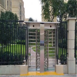


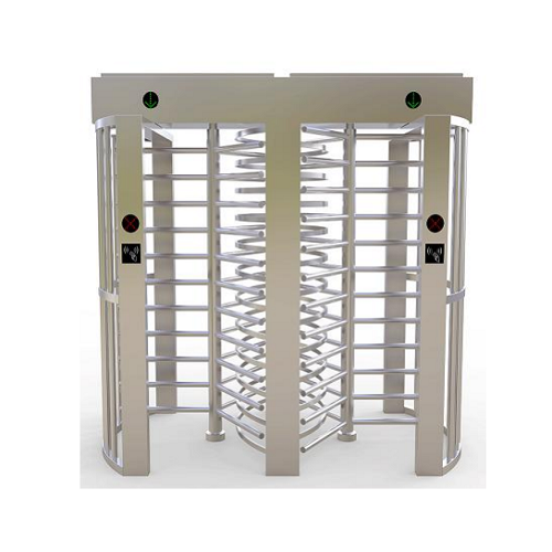
 Double Lane Full Height Turnstile Gate for Residential Area
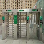 Dual Lane Tandem Full Height Turnstile Gate for Industry Park
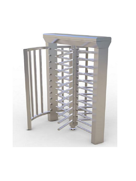
 Single Full Height Security Turnstile for Office Buildings
 Motorised Double Full-Height Turnstile for Office Buildings
Please leave a message if you are interested in this model