The entrance turnstile with revolving door
It relates to an entrance turnstile with a revolving door that can be rotated about a first axis of rotation with protruding locking elements for blocking a first passage area and with a door leaf that can be pivoted about a second axis of rotation and is designed such that in a closed position it blocks the passage through a second passage area adjacent to the first passage area of the revolving door and allows the locking elements of the revolving door to pass when the door is rotated, and such that it can be rotated or pivoted about the second axis of rotation into an open position in which it clears the passage through the second passage area.
A revolving door is designed here with a turnstile bars that protrude radially from a first axis of rotation and are arranged one above the other, which form two or three vertical wings distributed around the axis of rotation, and with a circular arc-shaped boundary on one side of the first passage area. A door leaf is designed in the manner of a small locking rake with bars arranged one above the other at a distance and extends between a post that is remote from the circular arc-shaped boundary and the axis of rotation of the revolving door. The door leaf can be pivoted in the area of the post about a second axis of rotation between a closed position and an open position, whereby the door leaf closes the second passage area, which includes the dead space of the revolving door, in the closed position and the gaps between the bars of the door leaf allow the bars of the revolving door to pass through unhindered when it rotates.
In the entrance turnstile, in order to open the second, extended passage area with the dead space of the revolving door, for example to enable barrier-free passage for people with disabilities and/or bulky equipment past the first passage area of the revolving door, the door leaf must be opened by hand and pivoted through a pivot range of 90° from the closed position to the open position. The revolving door is then rotated into a position in which the two (or two of three) vertical wings are approximately parallel to the open door leaf, so that the second passage area is open between the door leaf and the revolving door. A disadvantage of this known turnstyle gate is that the door leaf can only be pivoted from the stop in a door frame into the open position in one direction, which is particularly problematic if the open position is opposite to the desired passage direction. In the case of people with disabilities, such as wheelchair users, or when there is a large crowd of people at the security gate, opening the door against the direction of movement of the person or people is problematic or even impossible.
One possible solution is to install a release device for the door leaf at a sufficient distance from the security gate in conjunction with a motor-driven drive device for the door leaf. However, this solution is structurally complex because the release device has to be connected to the security gate turnstile and protected, and depending on the situation at the security gate, it may not be advantageous either because here the door leaf is always opened in the same direction using the drive device.
It aims to solve at least some of these problems in a generic turnstile equipment with a revolving door and a door leaf.
To solve this problem, it proposes an entry turnstile with the features of claim 1. Preferred embodiments are specified in the dependent claims.
The high entry-exit turnstile therefore comprises a revolving door that can be rotated about a first axis of rotation in opposite directions with protruding locking elements for blocking a first passage area, and a door leaf that can be pivoted about a second axis of rotation, which is designed in such a way that in a closed position it blocks the passage through a second passage area adjacent to the first passage area and allows the locking elements of the revolving door to pass when the door is rotated, and in such a way that it can be rotated or pivoted about the second axis of rotation into an open position in which it opens the passage through the second passage area, the metal security gate being characterized in that the door leaf can be rotated about the second axis of rotation from the closed position in opposite directions.
Due to the possibility of both opening the door leaf from the closed position and rotating the revolving door in both directions, the second passage area blocked by the door leaf in the closed position, which also includes the dead space of the revolving door and serves to bypass the first passage area of the revolving door in certain situations, can always be opened in the passage direction depending on the desired passage direction, without the door leaf or a leaf of the revolving door having to be moved against the passage direction to open it. This means that the passage can also be opened for people who are already in the area of the turnstyle door, i.e. in particular for people with a mobility handicap or in the event of a large crowd of people. In addition, a device for opening and/or operating the door leaf can be arranged in the immediate area of the entrance turnstile gate, because even if it is operated close to the personal lock, the person does not have to provide space for the door leaf or revolving door to open after operation.
Preferably, the first and second rotation axes are arranged in the area between the first passage area of the revolving door and the second passage area of the door leaf and further preferably concentrically to one another. With this arrangement, the rotation axes and any drive device provided can be provided in a central and easily protected central area of the morden turnstile.
In particular, the arrangement of the rotation axes in this way enables the particularly preferred possibility that the first and the second rotation axes can be selectively coupled to one another via a coupling device and/or the use of a particularly common drive with which the revolving door and the door leaf can be driven to rotate about their respective rotation axes, whereby the door leaf can be selectively mechanically coupled to and decoupled from the drive. The coupling of the two axes enables the simple and simultaneous operation of the door leaf and the revolving door when the passageway bypassing the passage area of the revolving door is to be opened and closed by the door leaf. This advantage has an advantageous effect both with manual operation and with motor-assisted operation of the revolving door and the door leaf. In addition, this arrangement also enables the particularly advantageous use of a drive used jointly for the revolving door and the door leaf and reduces the complexity of the drive and thus the costs of the electronic turnstile.
As an alternative to the common drive, the revolving door and the door leaf can each be driven by their own drive for rotation about their respective axis of rotation and the drives can preferably be mechanically coupled and/or synchronized with one another.
A preferred embodiment of the entrance gate turnstile is one in which the locking elements of the revolving door form a plurality of locking wings arranged around the first axis of rotation, preferably two locking wings arranged offset by approximately 180° from one another with respect to the first axis of rotation, and the revolving door and the door leaf can be rotated about their respective axis of rotation, while two locking wings of the revolving door are essentially aligned with the door leaf. This embodiment prevents, for example, rods of the wings of the revolving door from protruding into the passage area when the door leaf is opened and could lead to an obstruction of the passage.
Preferably, the security turnstile is provided with a control system which can interact with the drive(s) of the revolving door and the door leaf in order to rotate the locking leaves of the revolving door into the essentially aligned position with the door leaf and/or to rotate the revolving door and the door leaf together and simultaneously about their respective axis of rotation while maintaining this aligned position in order to pivot the door leaf between its closed and open positions. Such a control system enables simple operation and triggering of the opening process, so that a user does not have to worry about coordinating the operation of the two interacting door elements – revolving door and door leaf – of the security lock.
Preferably, a device is provided for locking and remotely unlocking the door leaf in the closed position, so that the passage through the personnel lock can also be controlled remotely, for example from a remote control station.
In particular in a design with a motor drive for the revolving door and the door leaf, the device for locking and unlocking the door leaf is preferably designed such that it can interact with the control to unlock the door leaf before the revolving door and the door leaf are rotated together.
In the following, preferred embodiments are explained by way of example with reference to the accompanying drawings, in which:
Fig.1 to 4 an embodiment of the entrance turnstile in the different operating positions and each in a top view and plan view
Fig.5 to 7 show the embodiment of the entrance turnstile in different operating positions and locking states
Fig.8 a first variant of a drive of revolving door and door leaf in the entry turnstile gate
Fig.9 shows a second variant of a drive for a revolving door and door leaf in an entrance turnstile
The entrance turnstile 1 shown in Figures 1 to 4 in various operating positions according to one embodiment has, for example similar to the security turnstile system, a revolving door 2 with a turnstile with bars 21 projecting radially from a first axis of rotation 22 and arranged one above the other, which form two vertical wings 23a, b distributed around the axis of rotation and offset by 180° from one another, and with a circular arc segment-shaped boundary 24 that delimits one side of the first passage area A. A pivoting door 3 with a door leaf 33 is designed in the manner of a locking rake with bars 31 arranged one above the other at a distance and extends from the area of the axis of rotation 22 of the revolving door 2 on the other side of the first passage area A away from it and closes off a second passage area B, which also includes the so-called “dead space” of the revolving door, but is usually larger than this. For this purpose, the spaces between the bars 31 of the door leaf 33 are arranged offset from the bars 21 of the turnstile of the revolving door 2, at least in the area of the dead space, in such a way that they allow the bars 21 of the revolving door 2 to pass through unhindered when it rotates. In the part of the door leaf 33 adjoining the dead space, the bars can be arranged in a different orientation, e.g. vertically, and/or at closer intervals, as shown in Fig.1.
The door leaf 33 of the swing door 3 can be pivoted about a second pivot axis 32 between a closed position and an open position in the area of the pivot axis 22 of the swing door 2, i.e. in the area between the first passage area A and the second passage area B, whereby the door leaf blocks the second passage area B in the closed position and releases it in the open position, so that people can bypass the first passage area A of the swing door and pass through the personnel lock through the second passage area B, for example to enable barrier-free passage for people with disabilities and/or bulky equipment. The concentric arrangement of the first and second pivot axes, which will be explained later, is particularly preferred.
Both the revolving door 2 and the door leaf 33 of the pivoting door 3 can be rotated or pivoted independently of one another about their respective rotation axes 22, 32 in opposite directions, i.e. clockwise and counterclockwise with respect to the plan view in Figures 1 to 4. To open the second passage area B, the revolving door 2 and the door leaf 33 of the pivoting door 3 can be selectively coupled to one another, preferably via a coupling device 16, so that they can be rotated or pivoted together.
This arrangement enables various characteristic operating positions and movement sequences of the full height turnstile gate, which are shown in Figures 1 to 4 in plan and top views respectively.
Figure 1 shows a closed position in which the passage area A is blocked in the middle by one wing 23a of the revolving door 2 and the passage area B is blocked by the other wing 23b of the revolving door 2 and the door wing 33 of the swing door 3, which are aligned with each other. This position is the starting position of the turnstile operation of the revolving door 2 when the door wing 33 remains locked in its closed position and the turnstile is released or can be rotated to only release the passage area A depending on the rotation position of the turnstile (see also Figures 2 and 5). In this position, the bars 31 of the door wing 33 also function as deflection bars to seal off the dead space of the revolving door.
Figures 3 and 4 show two positions (hinged on the left and right) of a door operation of the full height turnstile barrier gate, in which the passage area A is blocked by a leaf 23a, b of the revolving door 2 at the two entrances of the circular arc segment-shaped boundary 24 extending approximately over a semicircle, and the passage area B is released by pivoting the door leaf 33 of the pivoting door 3 into one of its open positions. The door operating positions are achieved by rotating or pivoting the revolving door and the door leaf, preferably together and coupled to one another, by 90° in an aligned position.
The coupling of the first and second rotation axes 22, 32 in order to move the revolving door and the door leaf together into the door operating positions is preferably carried out with a coupling device that can be activated selectively. This can be done, for example, via a switchable magnetic coupling or a mechanically operated coupling. The provision of a coupling device is useful regardless of whether a drive is also provided for the revolving door and/or the door leaf. In conjunction with a drive, however, additional advantages are offered, which are described below.
Particularly preferred in this context is an embodiment of the full height turnstile 1 in which the revolving door 2 and the door leaf 33 can be driven by a common drive 5 to rotate about their respective axes of rotation 22, 32 and the door leaf 33 can be selectively mechanically coupled to and decoupled from the drive 5. An example of such a common drive is shown in Figure 8. The drive 5 is here, for example, an electric motor, the axess turnstile of the revolving door 2 being preferably permanently connected to the drive 5 via a shaft 12 forming the first axis of rotation 22 and, after corresponding actuation, being driven in a manner known per se via a switch or sensor. The door leaf 33 of the swing door 3 is connected to a hollow shaft 14 which forms the second axis of rotation 32. The shaft 12 of the revolving door is concentric to the hollow shaft 14 and passes through it. The hollow shaft 14 can be reduced to a ring depending on the installation situation.
A coupling device 16 is provided between the shaft 12 and the hollow shaft 14, which has a rotor 16a connected to the shaft 12 in a rotationally fixed manner and a stator 16b connected to the hollow shaft 14 in a rotationally fixed manner and a coupling means 16c, via which the rotor and stator can be selectively connected and separated or brought into and out of engagement with one another. A spring 13 presses the rotor 16a away from the stator 16b when the coupling means 16c is not actuated. An electromagnet or a remotely operable mechanical lock can serve as the coupling means for the rotationally fixed coupling of the stator and rotor.
Figures 5 to 7 show the functional sequences between the different operating modes of the full height security turnstile and in the transition phases from one operating mode to the other, with a closed lock symbol representing a locked state and the open lock symbol representing an unlocked state. Figure 5 shows the closed position of the door leaf 33 – the second passage area B is thereby blocked. The lock is ready for passages through the turnstile, i.e. through the first passage area A. In this operating state, the coupling device 16 is open and the turnstile of the revolving door 2 can rotate unhindered in the hollow shaft 14 of the door leaf 33 relative to its axis of rotation 32 about its own first axis of rotation 22. The door leaf 33 is locked in this closed position with a locking device 4. In a preferred embodiment, the locking device 4 is an electronic swing door opener, which locks the door leaf in the closed position and can be selectively unlocked by a remote control.
Figure 10 shows the transition from turnstile operation to door operation in anti-clockwise movement in a top view. This change in operating mode is triggered by an actuating device, for example a key switch 6 at the entrance to the passage area A at the personnel lock and/or at the locking device 4 of the door leaf and/or at a position remote from the full height optical turnstile, for example in a control center. When the actuating device is activated, the locking device 4 of the door leaf 33 is unlocked and the coupling device 16 is activated. If the leaves 23a,b of the revolving door are not yet aligned with the door leaf 33, the drive 5 can be actuated before the coupling device is activated and the locking device 4 is unlocked in order to first rotate the revolving door 2 into the aligned position with the door leaf. After activation of the coupling device, the drive 5 moves both the turnstile of the revolving door 2 and the door leaf 33 together about their respective axes of rotation until the door leaf is in its open position (see Figure 6), in which the passage area B is released and the passage area A is blocked. This open position is held, for example, by a self-locking of the drive 5. If necessary, a locking device can be provided for this position.
Figure 7 shows the return of the lock to the turnstile mode. The coupling device 16 remains closed and the locking device 4 of the door leaf remains open. The drive 5 returns the door leaf 33 and the turnstile of the revolving door 2 to the starting position shown in Figure 15, whereupon the locking device 4 locks the door leaf and the coupling device 16 removes the coupling of the rotation axes of the revolving door and door leaf, so that the lock is again available for passages through the first passage area A at the access control turnstile.
Figure 9 shows an alternative drive design for the security entry gate. As with the drive design in Figure 8, the automated turnstile of the revolving door is driven by the drive 5 via the shaft 12, which is guided through the hollow shaft 14 of the door leaf. However, the movement of the door leaf about its axis of rotation (the hollow shaft) is carried out by a separate drive 10, which transmits the drive torque to the hollow shaft 14 via a transmission 15 (which is shown schematically here by two gears) or a gear box. With this drive design, a coupling device can be dispensed with. In this variant, the drives 5, 10 can preferably be synchronized with one another, for example via a control system, so that after the door leaf is unlocked, the wing door and the revolving door can rotate together into the door operating position described above. The variant with two drives has the advantage that the first drive 5, which is usually used much more frequently, only rotates the turnstile and does not have to cope with the relatively high mass of the swing door and its large mass moment of inertia when moving to the door operating position.
In a variant not shown, the second drive could also be implemented by a pre-tensioned spring mechanism which, after the door leaf 33 has been unlocked, automatically pushes it into the open position and supports the simultaneously activated drive of the canopy turnstile canopy. In this variant, the door leaf would have to be returned to the closed position by hand.
1. Entrance turnstile
2. Revolving door
3. Swing door
21. Lattice bars (deflector bars) of the revolving door
22. (first) axis of rotation
23. a,b Wing of the revolving door
24. Circular arc segment-shaped boundary
31. Lattice bars (deflector bars) of the door leaf
32. (second) axis of rotation
33. Door leaf of the swing door
4. Actuating and/or locking device
5. Drive of the revolving door
6. Actuating device
10. Drive of the door leaf
12.Shaft of the entry turnstile
13. Spring
14. Hollow shaft of the door leaf
15. Transmission
16. Coupling
16. a Rotor
16b. Stator
16c. Coupling means
A. Passage area of the revolving door
B. Passage area of the swing door
Claims
1. The entrance turnstile(1), with a revolving door (2) which can be rotated about a first axis of rotation (22) in opposite directions and has protruding locking elements (21) for blocking a first passage area (A), and a door leaf (33) which can be pivoted about a second axis of rotation (32) and which is designed such that, in a closed position, it blocks the passage through a second passage area (B) adjacent to the first passage area (A) and allows the locking elements (21) of the revolving door (2) to pass when the door is rotated, and such that it can be rotated or pivoted about the second axis of rotation (32) into an open position in which it opens the passage through the second passage area (B), characterized in that the door leaf (33) can be rotated about the second axis of rotation (32) from the closed position in opposite directions.
2. The entrance turnstile (1) according to claim 1, wherein the first and the second rotation axes (22, 32) are arranged in the region between the first passage area (A) and the second passage area (B) and are preferably arranged concentrically.
3. The entry turnstile (1) according to claim 1 or 2, wherein the first and second rotation axes (22,32) can be selectively coupled to one another via a coupling device (16).
4. The floor-to-ceiling turnstile (1) according to one of claims 1 to 3, wherein the revolving door (2) and the door leaf (33) can be driven by a common drive (5) to rotate about their respective axis of rotation (22, 32) and the door leaf (33) can be selectively mechanically coupled to and decoupled from the drive (5).
5. The electrical turnstile (1) according to one of claims 1 to 3, wherein the revolving door (2) and the door leaf (33) can each be driven by their own drive (5, 10) for rotation about their respective axis of rotation (22, 32) and the drives (5, 10) can preferably be synchronized with one another.
6. The pedestrian security turnstile (1) according to one of claims 1 to 5, wherein the locking elements (21) of the revolving door (2) form a plurality of locking wings (23a, 23b) arranged around the first axis of rotation (22), preferably two locking wings (23a, 23b) arranged offset by approximately 180° from one another with respect to the first axis of rotation (22), and the revolving door (2) and the door leaf (33) are rotatable about their respective axis of rotation (22, 32), while two of the locking wings (23a, 23b) of the revolving door (2) are substantially aligned with the door leaf (33).
7. The automatic pedestrian turnstile (1) according to claim 6 in conjunction with claim 4 or 5, wherein a control is provided which can interact with the drive(s) (5,10) of the revolving door (2) and the door leaf (33) and optionally the coupling device (16) in order to rotate the two locking leaves (23a,23b) of the revolving door (2) with the door leaf (33) into the substantially aligned position and/or to rotate the revolving door (2) and the door leaf (33) together about their respective axis of rotation (22,32) while maintaining this aligned position in order to pivot the door leaf (33) between its closed and open positions.
8. The accessible turnstile (1) according to one of claims 1 to 7, wherein a device (4) for locking and remotely unlocking the door leaf (33) in the closed position is provided, preferably in conjunction with a/the control to unlock the door leaf (33) before the revolving door (2) and the door leaf (33) are rotated together.


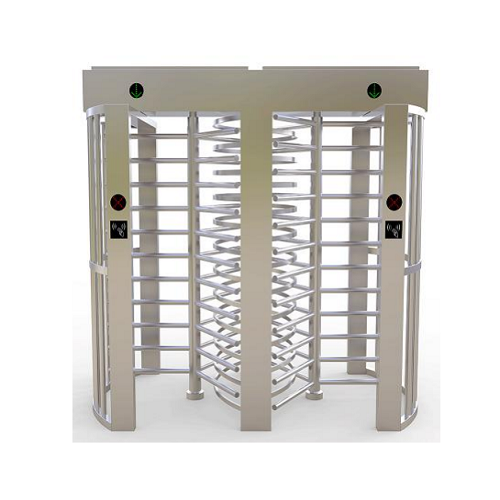
 Double Lane Full Height Turnstile Gate for Residential Area
 Dual Lane Tandem Full Height Turnstile Gate for Industry Park
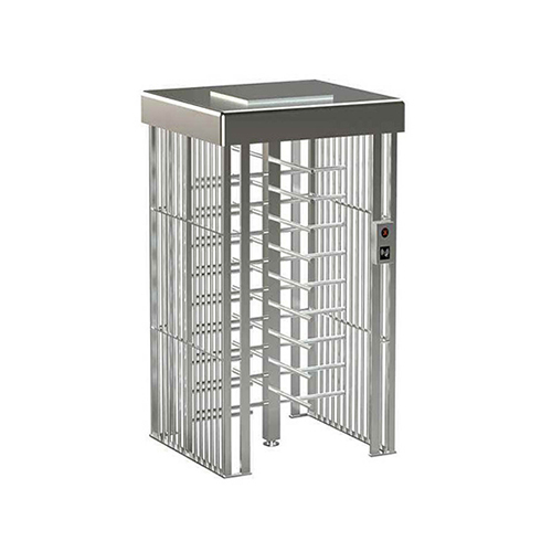
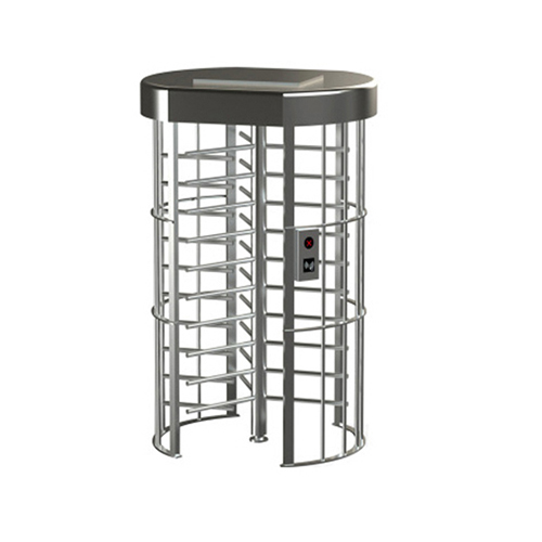
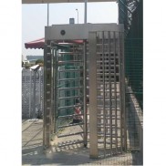
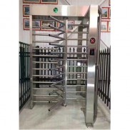 Single Full Height Security Turnstile for Office Buildings
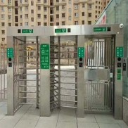
 Motorised Double Full-Height Turnstile for Office Buildings
Please leave a message if you are interested in this model