The standard of vehicle parking control equipment
Specification for pay-on-foot parking control equipment
Committees responsible for this
British Standard
The preparation of this British Standard was entrusted by Technical Committee B/509, Road equipment, to Subcommittee B/509/20, Vehicle parking control equipment, upon which the following bodies were represented:
Association of Chief Police Officers of England and Wales
Association of District Councils
Association of London Authorities
Association of Metropolitan Authorities
British Parking Association
Department of Transport (Highways Agency)
Institution of Civil Engineers
Institution of Highways and Transportation
Parking Committee for London
Royal Automobile Club
Co-opted members
Foreword
This Part of BS 6571 has been prepared by Subcommittee B/509/20. It is a new Part of BS 6571.
Other Parts are as follows:
Part 1 Specification for coin operated clockwork barrier gate arms
Part 2 Specification for electrically powered arm barrier gates
Part 3 Specification for pay and display equipment
Part 4 Specification for barrier type parking control equipment
Part 5 Guide to the requirements for non-coin operated apparatus for use with parking control equipment
Further Parts are under consideration, in particular:
Part 7 Specification for parking discs including orange badges
Part 8 Specification for pre-purchased parking vouchers
Part 9 Specification for in-car electronic devices
Part 10 Code of practice for ancillary parking equipment and parking signs
Whilst it is not within the scope of this standard, attention is drawn to the guidance of the Design Council on the aesthetic qualities of street furniture.
Product Certification. Users of this British Standard are advised to consider the desirability of third party certification of product conformity with this British Standard based on testing and continuing product surveillance which may be coupled with assessment of a supplier’s quality systems against the appropriate Part of BS 5750.
Enquiries as to the availability of third party certification schemes are forwarded by BSI to the Association of Certification Bodies. If a third party certification scheme does not already exist, users should consider approaching an appropriate body from the list of Association members.
Compliance with a British Standard does not of itself confer immunity from legal obligations.
Specification
1 Scope
This Part of BS 6571 specifies requirements for equipment for use with pay-on-foot parking control systems for off-street car parks in respect of the following items:
a) an automatic payment station;
b) a manned cashier payment station;
c) a manned management payment station;
d) a ticket reading mechanism to control entry/exitbarrier gate operators.
This equipment would be installed to operate in conjunction with driveway barrier gate, card acceptance units and ticket dispensing mechanisms.
2 References
2.1 Normative references
This Part of BS 6571 incorporates, by dated or undated reference, provisions from other publications. These normative references are made at the appropriate places in the text and the cited publications are listed on the inside back cover. For dated references, only the edition cited applies; any subsequent amendments to or revisions of the cited publication apply to this Part of BS 6571 only when incorporated in the reference by amendment or revision. For undated references, the latest edition of the cited publication applies, together with any amendments.
2.2 Informative references
This Part of BS 6751 refers to other publications that provide information or guidance. Editions of these publications current at the time of issue of this standard are listed on the inside back cover, but reference should be made to the latest editions.
3 Definitions
For the purposes of this Part of BS 6571 the following definitions apply.
3.1 ticket dispenser
Mechanism designed to mark and/or encode and issue a ticket for parking. It may incorporate additional features, e.g. `back-off ticket’ cancellation, invalidation, swallowing, multi or single slot device acceptance units, intercom.
3.2 automatic payment station
Unit designed to accept, read and verify the information encoded on the ticket issued by a ticket dispenser, calculate the fee due, accept valid payment and provide a ticket which will operate the exit automatic vehicle barrier by either recoding the original ticket or issuing an alternative ticket.
3.3 manned cashier payment station
Manned payment station which enables the customer to pay on foot the fee computed from the entry ticket with process facilities for ticket validation which provides a ticket which will operate the exit automatic traffic barrier by either recoding the original ticket or issuing an alternative ticket.
3.4 manned management station
Facility for managing and operating a car park barrier system and, where not otherwise provided, including the facilities defined in 3.3.
3.5 ticket reading mechanism
Device for reading a suitably encoded ticket from an automatic payment station or manned cashier payment station or ticket dispenser, and capable of transmitting a signal to operate the parking barrier for car
3.6 ticket
Paper, card or plastic document issued on entry to the car park, or by the automatic or manned payment stations, which carries encoded or machine-readable information.
3.7 accuracy of timing
Period, in seconds, over a course of a month in respect of the real time control.
3.8 real time control
Device to establish chronological time within the equipment for the purpose of parking fee calculations.
3.9 real time display
Device for visibly displaying current time, in hours and minutes, from the real time control.
3.10 coin/token acceptance
Function involving the correct operation of the equipment as a result of the insertion of a valid coin or token.
3.11 bank note acceptance
Function involving the correct operation of the equipment as a result of the insertion of a valid bank note.
3.12 device acceptance
Function involving the correct operation of the equipment as a result of the correct use of a valid payment device of a type or types agreed by the operator with the manufacturer.
3.13 valid coin
Any coin accepted as legal tender of a denomination agreed by the operator with the manufacturer.
3.14 valid bank note
A bank note accepted as legal tender of a value agreed by the operator with the manufacturer.
3.15 valid token
Medium of transaction agreed by the operator with the manufacturer with no official value recognized by the banking system but able to serve as payment for a transaction.
3.16 payment device
Object other than a coin or a token able to complete a valid transaction and agreed by the operator with the manufacturer.
NOTE. A payment device can be:
a) a period authorization device, which will permit parkingover a specified period; or
b) a decrementing value payment device which will permit thepurchase of a pre-defined value of parking or number ofoperations; or
c) a charge/credit card conforming to BS EN 27810, BS 7106,ISO/IEC 7812 and BS EN 27813 or those established for thepurpose of parking payment by an operator
3.17 tariff
Amount charged for a specific time period.
3.18 receipt
Document issued on request, acknowledging fee paid.
3.19 change giving unit
Mechanism that can give change or return the value of any aborted transaction either via a recycling unit, change hoppers or a combination of both.
3.20 coin/token box
Secure device for the collection of coins/tokens used for payment.
3.21 bank note box
Secure device for the collection of bank notes used for payment.
3.22 minimum audit facility
Means of indicating the total value of coins or tokens deposited in the cash box and of notes deposited in the bank note box and the number and value of transactions made by each device.
4 General requirements
4.1 The equipment shall be electrically operated from an external power source, although some functions may be supported and protected by an internal standby battery to deal with power failures.
4.2 The automatic pay station shall include the following features:
a) coin/token acceptance unit;
b) change giving facility;
c) secure coin/token box;
d) real time control;
e) real time display;
f) fee due display which may temporarily utilizethe real time display in conjunction with otherindicators;
g) facility to allow the pay station tocommunicate with a central control, other paystations and entry or exit points either directly and/or via a central controller;
h) system of voice communication so that theuser may ask for assistance from the operator;
i) facility to link to the real time centralmonitoring system;
j) facility to provide an audit trail;
k) facility to compute fees from encoded ticketdata and current time given by the real timecontrol;
l) facility to enable the user to cancel thetransaction at any stage prior to the issue of anexit ticket.
NOTE. Additional features may be provided where required by the purchaser, or at the option of the manufacturer, such as:
m) a device acceptance unit;
n) a bank note acceptance unit.
The coin/token acceptance unit and/or the device acceptance unit shall be capable of recording each individual coin or token acceptance or correct use of a payment device during a transaction. All amounts so inserted or remaining to be paid shall be displayed.
A reject unit or other mechanism shall be fitted and shall have a coin return cup capable of holding a minimum of 10 of each coin that is accepted by the unit.
4.3 The manned cashier payment station shall include the following features:
a) customer fee display;
b) cashier unit;
c) facility to provide an audit trail.
NOTE. Additional features may be provided where required by the purchaser, or at the option of the manufacturer, such as a device acceptance unit.
4.4 The charge/credit card payment facility when fitted shall include the following features:
a) charge/credit card acceptance and validationfacility;
b) receipt printer.
4.5 The equipment shall be arranged so that:
a) all variable displays are mounted between00 m and 1.40 m above surrounding ground level;
b) all fixed information plates are located between00 m and 1.80 m above surrounding ground level;
c) all coin/token or device acceptance externalfeatures and associated external controls arelocated between 1.0 m and 1.4 m above surrounding ground level;
d) all ticket reader slots or ticket issue slots shallbe positioned between 1.0 m and 1.4 m abovesurrounding ground level;
e) all push-buttons shall be positioned between0 m and 1.4 m above surrounding ground level;
f) any mounting plinth shall not protrude morethan 200 mm beyond the front face of the pay
4.6 The exit ticket reader shall have the following features:
a) ticket reader mechanism;
b) collection container for used or cancelledtickets;
c) warning indicator to show if ticket inserted isinvalid;
d) press for help’ push button operating anintercom for voice communication;
e) ticket insertion instruction guide if four-wayticket reading is not available.
NOTE. The ticket reader may incorporate an intercom activated by the push button or a facility to accept a period authorization device (see 3.16).
4.7 The fastenings used for fixing the equipment to its mounting shall be accessible only from within a lockable housing.
4.8 External push buttons shall be not less than 20 mm effective diameter.
4.9 The equipment and cash box housings shall be of sheet steel of welded construction with a minimum thickness of 2 mm or of material and construction of equivalent mechanical strength and security.
4.10 Locks for the coin and bank note boxes shall provide a system of security not less than that obtained from a multi-tumbler type of lock.
NOTE. The precise system of locking is not specified in this standard but should be agreed between the purchaser and the manufacturer. In this connection, attention is drawn to the possible use of selected key systems. The key(s) used to gain access to the internal equipment shall not allow entry into the coin orbank note boxes without the use of a further key.
4.11 Windows shall be manufactured either from toughened safety glass conforming to BS 857 or from plastics safety glazing material conforming to categories C or G in clause 4 of BS AU 182 : 1982.
4.12 The system shall be capable of issuing a receipt for a transaction.
4.13 Data in the audit facility shall only be recoverable by an authorized person using a key or a code.
NOTE. In addition to the facilities provided by a minimum audit facility (see 3.22), facilities may be provided to record:
a) equipment down time;
b) payments/device usage by tariff band;
c) payments/device usage by time of day/day of week;
d) accumulation of vehicles in the car park;
e) operational matters (e.g. door opening, cash box/bank notebox removals, emergency barrier openings);
f) any other matter required by the operator in agreement withthe manufacturer.
5 Electrical requirements
5.1 External power source
5.1.1 Electrical supply shall be a single or three phase supply.
NOTE. An additional operational standby system may be provided by agreement between the purchaser and the manufacturer.
5.1.2 All wiring shall be in accordance with BS 2754 and BS 7671.
5.1.3 Each piece of equipment shall be protected by a miniature circuit breaker or a residual current circuit device or by a labelled isolating switch to disconnect the power supply.
5.1.4 All items of metalwork within the equipment and mounting arrangement shall be bonded together to ensure adequate earthing.
5.1.5 The real time control and the audit facility shall be supported by means of either an automatically recharging battery or a primary cell. The real time control and the audit facility shall retain their memories for a period of not less than 7 days following a loss of the primary power source. If the system automatically returns to operating when the primary power source is re-established the machine shall record within the electronic memory, if fitted, the period(s) for which it was non-functional or the number of times for which it was non-functional. Otherwise the machine shall remain out of order until maintained by personnel.
NOTE. Primary cells, where used, should be changed at sufficient intervals to ensure these conditions are met.
5.2 Radio interference
The design of the equipment shall be such as not to create or be corrupted by telegraphic, telephone or radio interference and shall conform to BS 800.
6 Operational requirements
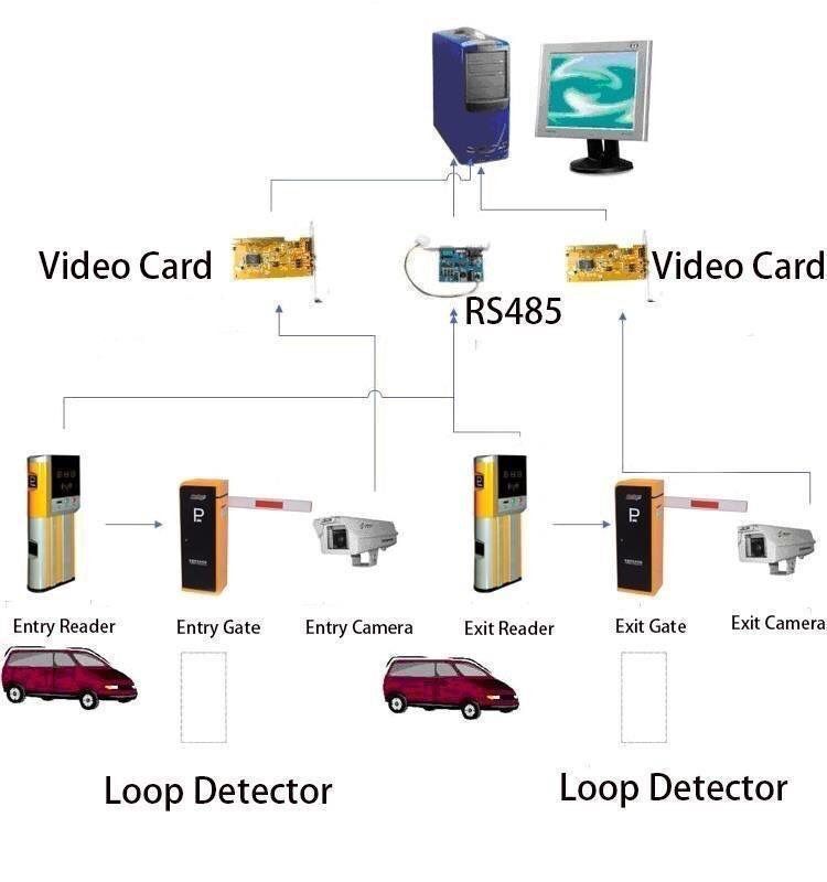
NOTE 1. A pay-on-foot system operates by issuing a suitably encoded ticket when a vehicle enters a car park. Before departure the ticket should be presented either at a manned cashier pay station or automatic pay station, where the fee due is calculated and payment accepted in a form acceptable to the car park operator. Upon settlement of the transaction an exit ticket is provided, either by re-coding the entry ticket, or issuing a new ticket which can then be used to operate the exit barrier gate
NOTE 2. In some installations the barrier may be operated direct by personnel at the manned pay station or by the automatic controls incorporated in equipment on exit lanes.
NOTE 3. For information on parking lot gate barriers and ticket issuing devices see BS 6571 : Part 4 which excludes the communication systems between constituent parts of the parking management system.
6.1 Accuracy of timing
Entry, exit and payment equipment shall be interconnected and use a common basis for the measurement of real time to an accuracy of 30 s/month. If communications links between items of equipment are broken the equipment shall be capable of measuring real time internally with an accuracy of 30 s/month, and once communications links are re-established, the measurement of real time in the equipment that has been isolated shall be automatically adjusted to the common measurement.
6.2 Minimum information to be coded on the ticket issued at the time of entry The time and date of issue shall be encoded at the time and date of entry. The time and date of entry shall also be printed on the ticket.
6.3 Minimum information to be coded on the ticket issued/re-issued at the time of payment At the time of payment the ticket issued at the time of entry shall be re-coded or a separate exit ticket shall be issued to show:
a) the time of payment, or
b) the time at the end of the tariff step period inwhich payment was made, or
c) the time of departure.
6.4 Fee calculation
When a valid entry ticket is presented at a payment station the fee due shall be calculated by comparing the time of arrival with the current time and the applicable tariff. The fee due shall be displayed. As payment is made the `fee due’ display shall decrement to zero; if over-payment is made the change giving unit shall return any over-payment.
6.5 Time of departure
To ensure that there is adequate time between payment being made and the vehicle being able to leave the car park, upon receipt of a valid payment a minimum grace period of 10 min shall be allowed for the vehicle to exit the car park after the expiry of the maximum time that would be allowed for the payment made.
NOTE. The grace period may be capable of being varied remotely by the car park operator to suit local circumstances throughout the period of operation of the car park.
6.6 Provision of receipt
Provision shall be made before exit for the supply of a receipt on demand from the user at the time that payment is completed. The following details shall be provided:
a) the full value of the parking fee paid;
b) the time and date of the transaction;
c) the location and machine reference;
d) any statutory details essential for charge orcredit card use;
e) car park operator, address and telephonenumber;
f) VAT number.
6.7 Coin/token acceptance
6.7.1 The coin/token acceptance unit shall be capable of returning, or not accepting, invalid coins or tokens outside the specified dimensions, tolerance and composition.
6.7.2 As each valid coin or token is inserted, the fee due shall be decremented until the payment is complete and the ticket is issued or the transaction is cancelled.
6.7.3 In the event of the transaction being cancelled or over-payment being made, the equivalent value of the payment or over-payment in coins or tokens inserted shall be returned to the user from the change giving unit.
6.7.4 The equipment shall refuse or return any coins, tokens or payment devices that are inserted during the ticket issue cycle.
6.8 Device acceptance
6.8.1 Where payment may be made using a payment device, the payment device reader shall be capable of identifying a valid means of payment, and of either decrementing the device by the charge paid or of reading information from the payment device allowing a record to be made which will allow the charge paid to be recorded against the device account (where appropriate).
6.8.2 Where provision is made for both valid coins and/or tokens and decrementing payment devices, provision shall be made for completion of a transaction by means of a combination of both means of payment or by successive devices.
6.8.3 The equipment shall be capable of displaying the number of unused or remaining units contained in a decrementing payment device.
NOTE 1. The method of recording the charge against a charge or credit card shall be a matter for agreement between the card issuing company, the operator and the manufacturer.
NOTE 2. Guidance on payment devices is given in BS 6571 : Part 5.
6.9 Bank note acceptance
The bank note reader mechanism shall be capable of reading and accepting the range of valid notes as agreed between the operator and the manufacturer.
The value of the note shall be recorded and the amount deducted from the fee due. Change due to the user from the difference between over-payment and the fee due shall be given in accordance with any specific notice that is displayed at the machine or by the operator.
NOTE. The bank note reader mechanism may or may not be fitted with an escrow facility. This is a matter for agreement between the operator and the manufacturer. Notes accepted as payment should be held in a bank note box.
7 Coin/token box
7.1 The coin/token box shall be housed either within a separate secure compartment or be capable of being further secured by a locking mechanism.
7.2 The coin/token box shall be designed to be capable of being monitored on the volume of coin/tokens accepted. When the coin/token box is full, the payment station shall go out of order and indicate this on the display described in 10.2.
7.3 All removable coin/token boxes shall have a self-closing lockable lid, actuated either upon withdrawal or upon unlocking the receptacle from its housing, to prevent access to the money contained therein.
7.4 A hand removable coin/token box shall have a maximum capacity of 6 l. If a larger capacity box is used means shall be provided to allow removal of the box in a safe manner.
7.5 The coin/token box shall be of sheet steel of welded construction with a minimum thickness of 1.5 mm or of other material and construction of equivalent mechanical strength and security.
8 Bank note box
8.1 Any bank note box shall be housed within a separate secure compartment or be capable of being further secured by a locking mechanism.
8.2 The bank note box shall be designed to be capable of being monitored on the number of bank notes accepted. When the bank note box is full the machine shall show the words `No bank notes’ on the display described in 10.2, and the note reading mechanism shall cease to function.
8.3 All removable bank note boxes shall have a self-closing lockable lid, actuated either upon withdrawal or upon unlocking the receptacle from its housing, to prevent access to the money contained therein.
8.4 The bank note box shall be of sheet steel of welded construction with a minimum thickness of 1.5 mm or of other material and construction of equivalent mechanical strength and security.
9 Change giving unit
9.1 The change giving unit shall be of the recirculatory type, e.g. self-filling from inserted coins or tokens, pre-loaded hoppers, or a combination of both as agreed between the operator and manufacturer.
9.2 The equipment shall indicate on a variable display whether the change giving facility is available for the next transaction. When the machine is not able to offer change it shall display a message to this effect on the variable display.
NOTE. The real time display or fee display may be used for these purposes.
9.3 If the change giving facility is displayed as being available, it shall be capable of catering for every transaction/change combination.
10 Displays
10.1 Real time display
10.1.1 The real time display shall show current time, in hours and minutes, either as 24 h time (00.00 to 23.59) or 12 h time (00.00 am to 11.59 am, 12.00 pm to 11.59 pm). Hours and minutes shall be separated by a colon and a leading zero shall be displayed for hours and/or minutes less than 10.
10.1.2 There shall be no variance between the real time displays on the constituent parts of the system in normal operation.
10.1.3 The real time display shall be shown in a steady manner.
NOTE. The colon separating hours and minutes may be intermittently displayed at a frequency of approximately once per second.
10.2 Payment displays
10.2.1 The payment display shall indicate the fee due in `£:p’ once an entry ticket has been properly inserted into the payment station. Once payment is complete, the display, or an alternative form of signalling, should prompt the removal of the exit ticket.
10.2.2 Where the payment display temporarily utilizes the real time display, `£:p’ characters shall be temporarily shown or there shall be an indication that they are temporarily applicable. The display shall revert to real time by the end of the ticket issue.
10.3 Visibility of displays
All displays, indicators, external acceptance features and controls shall be capable of being read or identified with normal or corrected vision at light intensities, measured at the immediate exterior surface of the equipment of between 5 lx and 100 000 lx. These requirements shall be assessed from a vertical/horizontal sighting position 1.0 m wide and located between 0.4 m and 1.0 m normal to the vertical centre line of the front face of the equipment and varying in height from 1.10 m to 1.75 m above the surrounding ground level.
NOTE 1. Surrounding ground level does not include any mounting plinth.
NOTE 2. It is permissible for the displays to be internally illuminated.
11 Ticket issue
11.1 The functions associated with the ticket issue shall allow staff to load tickets or ticket stock material, remove tickets and clear jams without mechanical assistance.
11.2 The equipment shall have the capacity to store a minimum of 3000 of each type of ticket used by the system.
11.3 A ticket shall be issued within 3 s of the ticket issuing function being activated.
11.4 In addition to the coded information, tickets issued shall be marked at the time of issue to show the following information:
a) issuing machine identity;
b) date and time of issue;
c) in the case of an exit ticket, the fee paid.
11.5 The following additional information shall be printed on the ticket:
a) name of the operator;
b) serial number if required by the operator;
c) any information required by legislation.
11.6 All information upon the ticket face, whether pre-printed or machine printed, shall remain legible for at least 14 days when exposed to direct sunlight for at least 8 h per day during this period.
11.7 Where inking ribbons or other inking systems are employed to print information upon the tickets issued, they shall be capable of being fitted without the use of mechanical assistance.
11.8 The minimum installed life of any inking ribbon or other printing medium or system shall be 40 000 tickets or 3 months, whichever is the shorter duration.
11.9 At the payment station, an exit ticket shall be issued within 3 s of the completion of the transaction.
12 Tickets
12.1 The size of a ticket shall be not less than 3800 mm² .
12.2 The ticket material shall:
a) have a minimum tensile strength of 25 N percentimetre width;
b) have a minimum mass of 50 g/m²;
c) be capable of being stored without deteriorationwithin the equipment.
NOTE. Requirement c) will be deemed to be met if the material does not show any deterioration which may affect its performance during issue or subsequent use.
12.3 Tickets shall be capable of removal from the ticket issuing unit with a force of not more than 10 N.
12.4 Encoded tickets shall have a read/write reliability not less than 99.99 %.
NOTE. As a normal transaction requires four read/write actions this equates to no more than four failures per 10 000 parking acts.
13 Information and instructions
13.1 Instructions given on the equipment shall be adequate to facilitate its correct operation. The information given shall include the following:
a) coins, tokens and devices that can be used;
b) instructions in case of equipment failure;
c) instructions on how to obtain help.
13.2 Where payment of the parking transaction can be made by credit card, the logo of the appropriate credit card companies shall be displayed on the payment station along with the instructions to enable correct use of the card.
13.3 Lower case characters shall be not less than 3 mm `x’ height. Digits and upper case characters shall be not less than 4 mm `X’ height. The colour of
the characters and the digits shall be in contrast to the background colour of the plate carrying this information.
NOTE. The height of the letter `x’ or `X’ defines the height of the other characters excluding ascenders and descenders of lower case characters.
14 Resistance to weathering
The equipment shall have a degree of protection equivalent to IPX3 when classified in accordance with BS EN 60529 which provides against the harmful effect of water when falling as a spray at an angle of up to 60 Ê from the vertical.
15 Type test
The equipment shall function correctly and remain within the limits specified in this standard when tested as described in annex A.
16 Marking
The equipment shall be clearly and indelibly marked externally with the following information:
a) the manufacturer’s name or trademark;
b) the number and date of this British Standard,e. BS 6571 : Part 6 : 1996 1)
17 System integrity
centralEach machine shall be capable of ticket validation in stand-alone mode, and not rely on the parking act history being stored.
Annexes
Annex A (normative)
Type test
A.1 Performance check
A performance check consists of a sequence of four transactions of different payment amounts repeated 10 times to yield a total of 40 transactions for each payment method which the machine will accept. A performance check verifies the following:
a) that the equipment will, within the terms of thisPart of BS 6571, correctly accept payment of alltypes allowed (including coins, tokens, bank notes and payment devices), display the correct information and issue a correctly printed encoded ticket for each transaction;
b) that the equipment will perform to the timingaccuracy specified in 6.1;
c) that the transactions will perform in a mannercausing change to be demanded from the machinewhere appropriate, and the machine to issue the correct change on each occasion;
d) that where a charge/credit card facility is fitted,equipment tests are carried out in accordance withthe requirements of the charge/credit card companies’ representatives.
A.2 Order of testing
The equipment is tested as follows.
a) Carry out a performance check at ambient
b) Place the equipment in a chamber and increasethetemperature to 50 ÊC
Over a period of not less than 1 hour . Leave at 50 ÊC for between 20 hours and 24 hours. Carry out a performance check.
c) Subjecttheequipment to damp heat at 40 ÊC and 95 % relative humidity (r.h.) for 4 h. Carry out a performance check.
d) Reducethetemperature of the equipment to 20 ÊC over a period of not more than 1 h and hold for a duration of 2 h. Carry out a performance check.
e) Reduce the temperature of the equipment to-10ÊC over a period of not less than 1 Leave at -10 ÊC for between 20h and 24h. Carry out a performance check.
f) Raise the equipment to ambient temperature.
g) Vibrate the equipment at a constant 0.5 GN inthree axes over a frequency range of 10 Hz to 150 Hzat a sweep rate of 17.5 Hz/min, pausing at major resonance for 5 min. Carry out a performance check
List of references (see clause 2 )
Normative references
BSI publications
BRITISH STANDARDS INSTITUTION, London
BS 800 : 1988 Specification for limits and methods of measurement of radio interference characteristics of household electrical appliances, portable tools and similar electrical apparatus
BS 857 : 1967 Specification for safety glass for land transport
BS 2754 : 1976 Memorandum. Construction of electrical equipment for protection against electric shock
BS 7671 : 1992 Requirements for electrical installations Ð IEE Wiring Regulations Ð Sixteenth edition
BS AU 182 : 1982 Specification for plastics safety glazing materials for use in road vehicles
BS EN 60529 : 1992 Specification for degrees for protection provided by enclosures (IP code)
Informative references
BSI publications
BRITISH STANDARDS INSTITUTION, London
BS 5750 : Quality systems
BS 6571 : Vehicle parking control equipment
BS 6571 : Part 4 : 1989 Specification for barrier type parking control equipment
BS 6571 : Part 5 : 1989 Guide to the requirements for non-coin operated apparatus for use with parking control equipment
BS 7106 : Guide to recording techniques for information on identification cards
BS 7106 : Part 1 : 1989 Embossing
BS 7106 : Part 2 : 1989 Magnetic stripe
BS 7106 : Part 3 : 1989 Guide to recording techniques for information on ientification cards Ð Location of embossed characters on ID-1 cards
BS 7106 : Part 4 : 1989 Location of read-only magnetic tracks Ð tracks 1 and 2
BS 7106 : Part 5 : 1989 Location of read-write magnetic track Ð track 3
BS EN 27810 : 1991 Guide to design, construction and use of identification cards
BS EN 27813 : 1992 Identification cards Ð Financial transaction cards
ISO and IEC publications
INTERNATIONAL ORGANIZATION FOR STANDARDIZATION (ISO) and INTERNATIONAL ELECTROTECHNICAL
COMMISSION (IEC), Geneva. (All publications are available from Customer Serives, BSI.)
ISO/IEC 7812 : Identification cards Ð Identification of issuers
ISO/IEC 7812-1 : 1993 Numbering system
ISO/IEC 7812-2 : 1993 Application and registration procedures


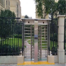


 Double Lane Full Height Turnstile Gate for Residential Area
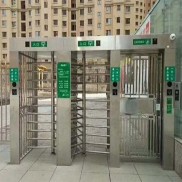 Dual Lane Tandem Full Height Turnstile Gate for Industry Park
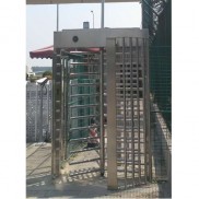
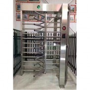 Single Full Height Security Turnstile for Office Buildings
 Motorised Double Full-Height Turnstile for Office Buildings
Please leave a message if you are interested in this model