Turnstyle door for controlling access to the secured areas
It relates to a turnstyle door for controlling the pedestrian access to secured areas, in which several locking arm holders with locking arms assigned to them are connected in a housing at equal angular intervals in a rotationally secure manner to a rotation axis running around a vertical line or approximately 45″ downwards, and in which the rotation axis can be locked against rotation in at least one direction of rotation by means of a controllable locking device in the locking position of the locking arm or unlocked for rotation in one direction, and each locking arm is held pivotably on its locking arm holder about a pivot axis running transversely to its longitudinal axis and also transversely to the rotation axis and is locked against pivoting by a locking device provided on the locking arm holder, but in the locking position can be moved to the release position by remote control using a fixed unlocking device to pivot away about the pivot axis.
The turnstyle doors of the aforementioned type which the locking arms are supported by rollers on a stationary curve, which has a section that can move transversely to the curved path in an area assigned to the locking position of the respective arm, which is held in the curved path by the locking device during normal operation of the barrier turnstile, but is moved out of the curved path when unlocking, so that the curved path is interrupted at this point and the locking arm in the locking position can fold down. This known design of the turn style door has the considerable disadvantage that the folded-down locking arm can only be folded back in the position in which it was folded down. Since the turnstile doors are usually equipped with a backstop, considerable difficulties arise if the turnstile is twisted after a locking arm has been folded down.

In order to remedy this, it has also become known to provide each locking arm with a locking lug, which interacts with an associated and spring-loaded rotary latch in such a way that the locking arm in the locking position can be moved into the folded-down position by pivoting the rotary latch using the fixed unlocking device and can be pivoted up again in any position, regardless of the position of the axess turnstile, and is automatically locked in the pivoted-up position.
The aforementioned design of the turnstyle door requires a very considerable amount of structural work for locking and unlocking and also has the additional disadvantage that the entire transmission of the forces acting on the locking arm must be transmitted via the relatively small locking surfaces of the rotary latch and the locking arm. This has a particularly unfavourable effect and leads to damage if someone tries to use force to operate the turnstile barrier arm in its locking position. Finally, with the known design of the barrier turnstile it is only possible to unlock the locking arm that is currently in the locking position, while if the turnstile continues to rotate the other locking arms can no longer be moved into the release position.
It is based on the object of designing a barrier arm turnstile of the type mentioned in the introduction in such a way that, despite the possibility of unlocking the locking arm in the locking position, a large force transmission from the locking arm via its holder to the rotation axis is achieved with very little construction effort and a permanently effective unlocking of the locking arm which is in the locking position is achieved.
To achieve the above object, the access control turnstile gate mentioned in the introduction is characterized according to the invention in that each locking device consists of a knee joint lever, which is hinged at one end to the locking arm, in relation to its cross-sectional area, to a bearing pin running at a distance and parallel to its pivot axis and at the other end to the locking arm holder and on which a spring acts, which tries to press the knee joint into an over-center position of the lever against a stationary abutment on the locking arm holder, and in that the unlocking device consists of a plunger on the locking arm holder that is longitudinally movable transversely to the knee joint lever, which engages with one end in the area of the knee joint on the knee joint lever and whose other end describes a movement path when the turnstile is rotated, in which a magnet-operated release lever fixed to the housing is held so that it can be pivoted in and out in the area of the locking position of the respective locking arm.
The intended support and locking of the locking arm by the knee lever is structurally simple and extremely robust. It allows the transmission of extremely large forces without loading the locking surfaces or requiring significant forces to be absorbed by the stationary abutment on which the knee lever rests. At the same time, the knee lever offers easy unlocking with very little effort and extremely short release paths, since the knee lever only has to be moved slightly into the bent position 9 to lose its supporting function.
Because the release lever for unlocking, which is fixed to the housing, is in the path of movement of the plunger acting on the knee lever when it is moved into the unlocking position, every locking lever that reaches the locking position is automatically moved into the folded-down position, so that the lock is automatically released for all locking arms that reach the locking position even if the exit turnstile continues to rotate. This is particularly important in emergencies in which people force their way through the passage formed by the turnstile and inadvertently set the turnstile in motion despite the locking arm being folded down.
It is particularly advantageous if the stationary abutment for the knuckle joint lever on the locking arm holder is designed as a sleeve and accommodates the longitudinally movable plunger of the unlocking device. In this way, the stationary abutment simultaneously serves as a guide for the plunger of the unlocking device.
In a further practical embodiment, the release lever is designed as a double-armed pivot lever, one arm of which is acted upon by an electromagnet and the other arm of which has a contact surface for the plunger. The double-armed pivot lever can be designed as an angle lever and requires only an extremely short distance to be moved into the various positions, so that correspondingly small magnets are sufficient to operate the pivot lever.
A particularly simple and stable design is achieved if each locking arm holder is U-shaped in cross-section and accommodates the respective locking arm, the associated knee joint lever with associated spring and the abutment as well as the plunger between the free legs. In this way, the components intended for locking and unlocking are simultaneously housed in a protected manner.
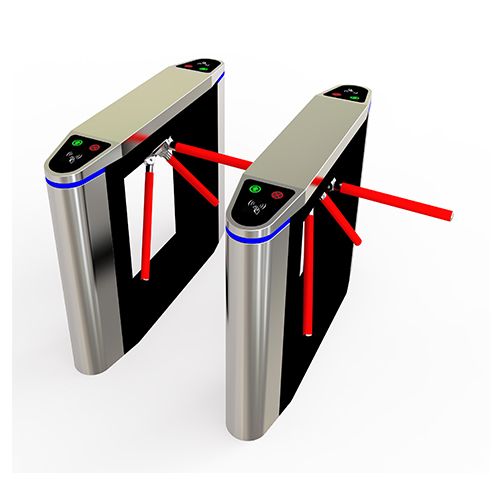
The drawings show an embodiment in a schematic representation.
Fig.1 is a partially sectioned top view of the turnstyle door, although for reasons of clarity only one locking arm is shown
Fig.2 is a detail of the arrangement according to Fig.1
Fig.3 is a schematic partial section from which the mode of operation of the unlocking device is clearly evident
In the figures, 1 designates the upper housing of a turnstile in which a rotary axis 2 is mounted, which accommodates several locking arm holders distributed around the circumference at equal angular intervals, of which only one locking arm holder 3 is shown in Fig.1. The rotary axis 2 can be locked against rotation in at least one direction of rotation or unlocked for rotation in one direction by means of a controllable locking device in a manner not shown in detail. In the exemplary embodiment, the locking arm holder 3 is U-shaped in cross section and is held with its middle leg 3a on a corresponding counter surface of the rotary axis 2. The free legs of the locking arm holder 3, which run parallel to one another, can be seen in Fig.3 and are designated there with 3b.
The locking arm holder 3 accommodates a locking arm 4 between its legs 3b. The locking arm 4 is mounted with its end facing the locking arm holder 3 between the walls 3b of the locking arm holder so that it can pivot about a pivot axis 5 held in the aforementioned walls, which runs transversely to the longitudinal direction of the locking arm 4 and also transversely to the longitudinal direction of the axis of rotation 2.
The locking arm 4 shown in Fig.1 assumes its horizontal locking position in this illustration and is held in this locking position by a knee joint lever, designated overall by 6. The knee joint lever is pivotally connected to the locking arm with its arm facing the locking arm 4 via a bearing pin 7. The bearing pin 7 runs at a distance and parallel to the pivot axis 5, with the pivot axis 5 and the bearing pin 7 being arranged approximately in the same cross-sectional plane of the locking arm 4. The arm of the knee joint lever 6, which is modified from the locking arm 4, is mounted via a further pivot axis 8 arranged in the side walls 8 and 3b of the locking arm holder 3. The knee joint 6a of the knee joint lever is supported in the over-center position shown in Fig.1 and 2 on a stationary abutment 9, which consists of a sleeve 9a which is held in a bore of a bridge member 9b connecting the side walls 3b of the locking arm holder 3.
Spring 10 is attached to the knee joint lever 6 9, which is attached to the middle leg 3a of the locking arm holder 3 and always tries to press the knee joint lever 6a into the over-center position shown in Fig.1 and 2.
In the example shown, the sleeve 9a of the abutment 9 accommodates a plunger 11 which can be moved longitudinally transversely to the knee joint lever 6 in the direction of the double arrow shown, which is aligned with one end on the knee joint 6a and with its other end describes a movement path when the turnstile rotates, in which a magnetically actuated release lever 12 fixed to the housing is held so that it can be swung in and out in the area of the locking position of the locking arm 4 shown in Fig.1.
Details of the magnet and the release lever 12 actuated by it can be seen in Fig.3. The magnet 13 shown there is held on a housing part 14. A push rod IS connected to the armature of the magnet 13 (not shown) can be moved in the direction of the double arrow 16, whereby the push rod 15 assumes the extended position shown in Fig.3 when the magnet is excited by a spring (not shown) provided in the magnet.
The release lever 12 is designed as a pivot lever and is mounted on a pivot axis 18 fixed to the housing. The push rod 15 engages one end of the pivot lever 12 via a bearing pin 17, while the other end of the pivot lever 12 forms a contact surface 19 for the plunger 11.
In the example shown, the pivot lever 12 is designed in its mode of operation like an angle lever, one leg of which forms the contact surface 19, while the push rod 15 engages at the end of the other leg.
When the magnet 13 is excited, the push rod 15 assumes the position shown in Fig. 3. In this position, the contact surface 19 of the angle lever 12 is outside the path of movement of the plunger 11 when the turn style gate is actuated.
When the magnet 13 is de-energized, the armature and thus also the push rod in Fig.3 are moved to the left by the spring located in the magnet housing, but not shown in the drawing, so that the contact surface 19 presses the plunger 11 of the rotary arm 4 in the locking position against the knee joint 6a of the knee joint lever 6 and moves the knee joint lever 6 from its over-center position shown in Fig.2 into the bent position. This removes the support of the locking lever 4 by the knee joint lever 6 and the locking arm 4 can fall downwards around the pivot axis 5 into the vertical position of its longitudinal axis due to its own weight.
With a further rotation of the outdoor security gate turnstile, the next locking arm is automatically unlocked and moves into the locking position, since during this movement the plunger 11 associated with this next locking arm runs onto the run-up surface 19 of the pivot lever 12 and then also acts in the manner described on the knee joint 6a of the knee joint lever 6 associated with the next locking arm and also moves this knee joint lever against the action of its spring 10 from the over-center position into the bent position.
In the area outside the locking position, all locking arms 4 can easily be moved back into the locking position in any position, in which a secure support is provided by the knee joint levers 6
In the example shown, the knee-joint lever 6 is designed in a particularly simple form. It consists of only two chain links connected to one another, as is usual in drive chains. The figures show that the knee-joint lever 6 as well as the abutment 9 and also the tappet 11 are protected and safely housed in the locking arm holder 3, which is U-shaped in cross-section.
Claims
1. A turnstyle door, in which several locking arm holders (3) with locking arms (4) assigned to them are connected in ahousing (1) at equal angular intervals in a rotationally secure manner to a rotation axis running around a vertical line or inclined downwards by approximately 45º, and in which the rotation axis can be locked against rotation in at least one direction of rotation by means of a controllable locking device in the locking position of the locking arm (4) or can be unlocked for rotation in one direction, and each locking arm (4) is held pivotably on its locking arm holder (3) about a pivot axis (5) running transversely to its longitudinal axis and also transversely to the rotation axis and is locked against pivoting by a locking device 9 provided on the locking arm holder (3), but in the locking position can be moved to the release position by remote control by means of a fixed unlocking device for pivoting away about the pivot axis (5), characterized in that each Locking device consists of a knee joint lever (6) which is articulated at one end to the locking arm (4), based on its cross-sectional area, on a bearing pin (7) running at a distance and parallel to its pivot axis (5) and at the other end to the locking arm holder (3) and on which a spring (10) acts which tries to press the knee joint (6a) into an over-center position of the lever against a stationary abutment (9) on the locking arm holder, and that the unlocking device consists of a plunger (11) which is longitudinally movable on the locking arm holder (3) transversely to the knee joint lever (6), which is oriented with one end in the area of the knee joint (6a) on the knee joint lever (6) and whose other end describes a movement path when the turnstile is rotated, in which a housing-fixed, magnet-operated release lever (12) is held so as to be able to swing in and out in the area of the locking position of the respective locking arm (4).
2. A turnstyle door according to claim 1, characterized in that the stationary abutment (9) for the knee joint lever (6) on the locking arm holder (3) is designed as a sleeve (9a) and accommodates the longitudinally movable plunger (11) of the unlocking device
3. A turn style door according to claim 1 or 2, characterized in that the release lever (12) is designed as a double-armed pivot lever, on one arm of which an electromagnet (13) acts and the other arm of which has a run-on surface (19) for the tappet (11).
4. A turnstyle door according to one of claims 1 to 3, characterized in that each locking arm holder (3) is U-shaped in cross section and accommodates the respective locking arm (4ț), the knee joint lever (6j) associated with it with the associated spring (10) and the abutment (9) as well as the tappet (11) between the free legs (3b).

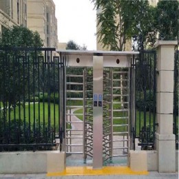
 Double Lane Full Height Turnstile Gate for Residential Area
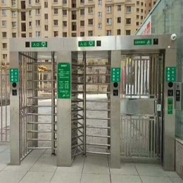
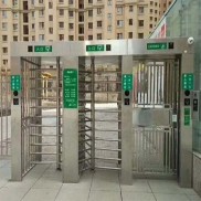 Dual Lane Tandem Full Height Turnstile Gate for Industry Park
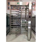 Single Full Height Security Turnstile for Office Buildings
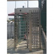 Motorised Double Full-Height Turnstile for Office Buildings




Please leave a message if you are interested in this model