Tripod turnstile boom barrier designed for counting persons
It relates to an access control device for people designed as a tripod turnstile boom barrier or a device for counting people designed as a turnstile according to the preamble of patent claim 1.
Access control devices for people and people counting devices designed as tripod turnstile barrier gates are known from the prior art. They include one, two or three locking arms which are connected in a rotationally fixed manner to a shaft that can be driven by an electric motor, the angles between the longitudinal axes of the locking arms being predetermined by the rotationally fixed connection.
In the case of access control devices for people designed as tripod gate turnstiles, when a valid access authorization is read out by means of a reading device, such an automatic turnstile is transferred from a blocked position to an released position by rotating the shaft to which the locking arms are connected in a rotationally fixed manner. In people counting devices designed as turnstiles, when a person is detected in the passage, this is done using suitable sensors, for example light switches, light barriers, radar sensors, etc. can be done, the shaft to which the locking arms are connected in a rotationally fixed manner is transferred from a locked position to an released position. After each pass, the value of a counter assigned to the direction of pass is increased by 1.
The entrance security barriers with three locking arms, the comfort when passing through is impaired due to the fixed angles between the locking arms, as luggage or strollers, for example, have to be lifted over one of the three locking arms. Since the angle between the longitudinal axes of two adjacent locking arms is usually 120°, the entire passage cannot be released because one locking arm always protrudes into the passage. However, entry turnstiles with three locking arms have the advantage that they ensure a sufficient lock and isolation effect, since a person is always between two locking arms when passing through.
Furthermore, tripod turnstile boom barriers with two locking arms are known, which are connected in a rotationally fixed manner to a shaft that can be driven by an electric motor, but which cannot eliminate the mentioned disadvantages of the turnstiles comprising three locking arms. Rather, safe isolation is impaired. Furthermore, turnstiles with a locking arm are known, which, however, moves very quickly to ensure isolation, on the one hand to clear the passage and on the other hand to ensure isolation, which increases the risk of injury to people passing through. Furthermore, wear is disadvantageously increased due to the high rotational speed of the mass of one locking arm; The high rotation speed is due to the fact that one locking arm has to be rotated 360 degrees per pass.
In addition, the turnstile automatic gates known from the prior art with two or three locking arms have the disadvantage that in an emergency or if the system is to be switched out of operation, the entire passage cannot be released.
A turnstile entry system with the features of the preamble of claim 1 is known. It is based on the object of specifying an access control device for people designed as a turnstile or a device for counting people designed as a turn style gate, which ensures good isolation while simultaneously releasing the entire passage in the event of a valid access authorization.
This task is solved by the features of patent claim 1. Further refinements and advantages emerge from the subclaims.
Accordingly, an access control device for people designed as a security turnstile gate or a device for counting people designed as a turnstile barrier is proposed, comprising a housing in which at least one drive means is arranged, which has two locking arms which can be driven by the at least one drive means and which are independent of one another and at the same or different speed can be driven and controlled.
The locking arms can be driven and controlled independently of one another in such a way that safe isolation and, with valid access authorization, release of the entire passage can be achieved.
The two locking arms can preferably be driven and controlled independently of one another in such a way that if there is a valid access authorization in the case of an access control device or if a person is detected in the passage in the case of a people counting device, the locking arm arranged in the direction of passage is in a starting position in front of a person, which blocks the passage, completely releases the passage in front of the person, the second blocking arm, which releases the passage in the starting position, being controlled in such a way that it blocks the passage behind the person in the direction of passage and the starting position is assumed again, in successive ones Starting positions the position of the locking arms is swapped.
In the case of an access control device for people designed as a tripod turnstile boom barrier, the access authorizations according to the prior art are recorded by a reading device of the access control device, with the validity being checked either locally or in a server connected to the access control device. The reading device can be, for example, an RFID reading device, a fingerprint scanner, an iris scanner, a barcode reader or a magnetic card reader. Furthermore, the reading device can be a reading device which can read access authorizations or IDs that are assigned to a valid access authorization from a customer medium using Bluetooth, Bluetooth Low Energy, WLAN or UWB standards. In addition, the turnstile can have several reading devices for different standards.
A first locking arm is arranged on a first shaft and a second locking arm on a second shaft, the first shaft being designed as a hollow shaft through which the second shaft is guided. The first and second shafts are arranged coaxially with one another.
The locking arms are connected to the respective shaft in a rotationally fixed manner at a predetermined angle to the shaft; For example, the locking arms are plugged or screwed onto the respective shaft. In an unclaimed embodiment, each shaft is assigned a drive means, which can be designed, for example, as an electric motor that drives the shaft. In further embodiments, the shafts can be driven hydraulically, pneumatically or electromagnetically. Preferably, the drive means is an electric motor with a gearbox connected upstream of the electric motor in the direction of power flow, the respective shaft being drivable by an output of the gearbox. The transmission can, for example, be designed as a planetary gear, as a spur gear or as a belt gear or as a combination of the aforementioned types of gear.
Only one drive means, for example an electric motor, is provided, which is preceded by a gearbox with two outputs, one output being connected to a shaft or releasably connectable by means of a controllable clutch, with the shafts against a predetermined resistance when the clutch is open are rotatable, which is selected such that the respective locking arm is held without external force and can be rotated with a defined torque. The gearboxes are designed in such a way that a desired control of the locking arms connected to the shafts is possible, in particular a control that enables safe isolation and, with valid access authorization, release of the entire passage.
The first shaft, which is designed as a hollow shaft, has a recess at its end facing away from the housing of the turnstile, from which the second locking arm assigned to the second shaft protrudes, the recess extending over a predetermined angular range, for example values between 200 ° and 300 ° can assume and wherein the first and second locking arms protrude axially along the central longitudinal axes of the coaxially arranged shafts from the same axial position. Here, the recess is arranged diametrically opposite the first locking arm connected to the first shaft. In this way, both locking arms can rotate along the same trajectory. Here, both locking arms can be moved independently of one another by an angular range that essentially corresponds to the angular range of the recess in the hollow shaft.
According to an unclaimed embodiment, the second locking arm, which is connected in a rotationally fixed manner to the second shaft, protrudes from the end of the first shaft, which is designed as a hollow shaft, facing away from the housing of the turnstile, so that any relative movement of the two locking arms to one another can be achieved. In this case, both locking arms rotate along different trajectories.
In the event of an emergency or if the tripod turnstile barrier gate is to be permanently switched out of operation, both locking arms can be controlled in such a way that they extend at the smallest possible angle to one another in the direction of the plane of the passage, so that the passage is released. In the event that the first shaft, designed as a hollow shaft, has a recess at the end facing away from the housing of the security gate turnstile, from which the second locking arm assigned to the second shaft protrudes, the smallest possible angle between the locking arms is approximately 360 ° minus the angular range of the recess . Accordingly, for example, the smallest possible angle between the locking arms is 80° in the event that the recess extends over an angular range of 280°. In the event that any relative movement of the two locking arms to one another can be achieved, the locking arms can be controlled in such a way that they are arranged essentially parallel to one another.
According to a further development, the bidirectional tripod turnstile has a battery which, in the event of a power failure, supplies the drive means, which are preferably designed as electric motors, with power, which ensures that in an emergency or if the turnstile is to be permanently switched out of operation, both locking arms can be controlled in this way are that they extend at the smallest possible angle to each other in the direction of the plane of the passage, so that the passage is unblocked.
The concept provides a drop arm turnstile which has the functionality of a conventional drop arm barrier with three locking arms in terms of the lock and isolation effect, but without the disadvantages in terms of comfort resulting from the presence of the three locking arms. It also ensures that the entire passageway is cleared in the event of an emergency.

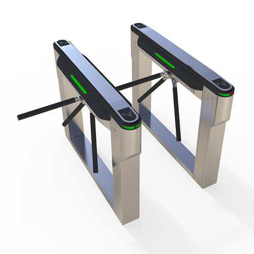
It is explained in more detail below using the attached figures, in which an access control device for people designed as a drop arm optical turnstile is shown. Examples of possible control of the locking arms during access control are shown; The control of the locking arms of the drop arm barrier turnstile can be varied according to the requirements. The examples shown also apply analogously to a device designed as a turnstilegate for counting people when a person is detected in the passage. In the accompanying figures, the upper left part is a front view, the upper right part is a top view, the lower left part is a side view and the lower right part is a view of a turnstile along the longitudinal axes of the first and second shafts. The direction of passage is from left to right in relation to the upper left part of the figures. Show it:
Figure 1: a tripod turnstile boom barrier, in which the first shaft, designed as a hollow shaft, has a recess at the end facing away from the housing of the turnstile over an angular range of 240 °, from which the second locking arm assigned to the second shaft protrudes, in a starting position in which the second blocking arm blocks the passage, the first blocking arm essentially clearing the entire passage, allowing a person to comfortably approach the second blocking arm, and the angle between the first and second blocking arms being approximately 120°;
Figure 2: a tripod turnstile boom barrier according to Figure 1, in which only the second locking arm is rotated by 30° in the direction of passage after a valid access authorization has been detected;
Figure 3: a tripod turnstile boom barrier according to FIG. 1, in which after the rotation of only the second locking arm by 30° in the direction of passage shown in FIG. whereby the entire passage is cleared to allow passage to the person approaching the first barrier arm in the initial position;
Figure 4: a tripod turnstile barrier gate according to FIG 1. whereby at the end of these rotational movements the second blocking arm extends substantially perpendicular to the plane of the passage and the first blocking arm begins to block the passage behind the person who has passed through;
Figure 5: a a tripod turnstile barrier gate according to Figure 1, in which the locking arms are rotated independently of each other according to the constellation shown in Figure 4, so that the starting position according to Figure 1 is reached, with the difference that the first locking arm blocks the passage, the second Locking arm releases the entire passage.
Figure 6: a tripod turnstile barrier gate according to Figure 1 to illustrate the position of the locking arms in an emergency or if the turnstile is to be permanently switched out of operation, the locking arms extending at the smallest possible angle to each other downwards towards the plane of the passage, so that the passage is released.
Figure 7: an unloaded tripod turnstile barrier gate, in which the second locking arm, which is non-rotatably connected to the second shaft, protrudes from the end of the first shaft, which is designed as a hollow shaft, facing away from the housing of the turnstile, so that any relative movement of the two locking arms to one another can be achieved in a starting position , in which the second blocking arm blocks the passage, the first blocking arm unblocking the entire passage, allowing a person to comfortably approach the second blocking arm;
Figure 8: a tripod turnstile barrier gate according to Figure 7, in which only the second locking arm is rotated by 30° in the direction of passage after a valid access authorization has been detected;
Figure 9: a tripod turnstile boom barrier according to FIG. 7, in which after the rotation of only the second locking arm by 30° in the direction of passage shown in FIG 7. whereby the entire passage is released to allow passage to the person approaching the first barrier arm in the starting position;
Figure 10: a tripod turnstile boom barrier according to FIG 7 whereby at the end of these rotational movements the second blocking arm extends substantially perpendicular to the plane of the passage and the first blocking arm begins to block the passage behind the person who has passed through;
Figure 11: a tripod turnstile boom barrier according to Figure 7, in which the locking arms are rotated independently of one another according to the constellation shown in Figure 4, so that the starting position according to Figure 1 is reached, with the difference that the first locking arm blocks the passage, the second locking arm releases the entire passage; and
Figure 12: a tripod turnstile boom barrier according to Figure 7 to illustrate the position of the locking arms in an emergency or if the turnstile is to be permanently switched out of operation, the locking arms with their longitudinal axes extending essentially parallel to one another downwards in the direction of the plane of the passage, so that the passage is opened.
In the attached figures, a turnstile tripod access control is designated 1, a housing of the turnstile 1 being designated 2, a first locking arm being designated 3 and a second locking arm being designated 4. Furthermore, 5 denotes the drivable shaft with which the first locking arm 3 is connected in a rotationally fixed manner, with 6 denoting the drivable shaft with which the second locking arm 3 is connected in a rotationally fixed manner.
A rfid tripod turnstile 1 comprises a housing 2 in which drive means are arranged. Furthermore, the tripod turnstile gate 1 includes two locking arms 3, 4 which can be driven by the drive means and which can be driven and controlled independently of one another and at the same or different speed, such that safe isolation and, with valid access authorization, release of the entire passage can be achieved.
Here, a first locking arm 3 is arranged on a first shaft 5 and a second locking arm 4 on a second shaft 6, the first shaft 5 being designed as a hollow shaft through which the second shaft 6 is guided, the first and second shafts 5, 6 are arranged coaxially to one another and the locking arms 3, 4 are connected in a rotationally fixed manner to the respective shaft 5, 6 at a predetermined angle to the shaft. Each shaft 5, 6 is assigned a drive means which can be controlled by a controller and which drives the shaft 5, 6. The shafts 5, 6 are preferably each driven by an electric motor.
In the example shown in Figures 1 to 6, the first shaft 5, designed as a hollow shaft, has a recess at its end facing away from the housing 2 of the turnstile 1, which is arranged diametrically opposite the first locking arm 3 connected to the first shaft 5, from which the the second locking arm 4 assigned to the second shaft 6 protrudes. In the example shown, the recess extends over 240°; According to the invention, the first and second locking arms protrude axially along the central longitudinal axes of the shafts 5, 6 arranged coaxially to one another when viewed from the same axial position.
In the starting position, which is illustrated with reference to Figure 1, the passage is blocked by the second blocking arm 4, with the first blocking arm 3 releasing the passage and protruding slightly into the passage to make it more difficult to climb under, whereby a person can comfortably reach the second blocking arm 4 can approach and where the angle between the first and the second locking arm is approximately 120 °. In the starting position, the blocking arm that does not block the passage, i.e. in the example shown in Figure 1 the first blocking arm 3, can completely release the passage; the corresponding position of the locking arm corresponds, for example, to the position of the first locking arm 3 in Figure 6.
If a person standing in front of the second blocking arm 4 blocking the passage and carrying a valid access authorization, which is detected by a reading device (not shown), the second blocking arm 4 is controlled in such a way that it is rotated by 30 ° in the direction of passage, like illustrated using Figure 2. By turning it another 90°, the entire passage is released to allow the person to pass through, as shown in Figure 3. In the example shown, the first locking arm 3 is not rotated during the rotation of the second locking arm 4. As part of further refinements, the first blocking arm can be rotated through a small angle, for example through 30°, in order to begin blocking the passage behind the person at this point in time.
Subsequently, the first and second blocking arms 3, 4 are rotated independently of one another, at the end of these rotational movements the second blocking arm 4 extends essentially perpendicular to the plane of the passage and the first blocking arm 3 begins to close the passage behind the person who has passed through. to lock; this situation is illustrated using Figure 4. In the further course, the locking arms 3, 4 are rotated independently of one another in such a way that the starting position according to FIG. 1 is reached, with the difference that the first locking arm 3 blocks the passage, with the second locking arm 4 releasing the entire passage.
In the event of an emergency or if the waist tripod turnstile1 is to be permanently switched out of operation, the locking arms 3, 4 are controlled in such a way that they extend downwards towards the plane of the passage at the smallest possible angle to one another, so that the passage is released. In the example shown, the smallest possible angle between the locking arms, due to the first shaft 5 designed as a hollow shaft, is 120° since the recess of the hollow shaft 5 extends over an angular range of 240°.
In the example shown in Figures 7 to 12, the second locking arm 4, which is non-rotatably connected to the second shaft, protrudes from the end of the first shaft 5, which is designed as a hollow shaft, facing away from the housing 2 of the turnstile 1, so that any relative movement of the two locking arms 3, 4 to each other can be achieved.
In the starting position, which is illustrated with reference to FIG. 7, the passage is blocked by the second blocking arm 4, with the first blocking arm 3 protruding slightly into the passage in order to make climbing under it more difficult. According to the invention, in the starting position, the blocking arm that does not block the passage, i.e. in the example shown in Figure 7 the first blocking arm 3, can completely release the passage.
If a person who is standing in front of the second blocking arm 4 blocking the passage and is carrying a valid access authorization, which is detected by a reading device (not shown), in the example shown, the second blocking arm 4 is controlled in such a way that it is rotated by 30 ° in the direction of passage is rotated, as illustrated in Figure 8. By turning it another 90°, the entire passage is released to allow the person to pass through, as shown in Figure 9. In the example shown, the first locking arm 3 is not rotated during the rotation of the second locking arm 4. As part of further refinements, the first blocking arm can be rotated through a small angle, for example through 30°, in order to begin blocking the passage behind the person at this point in time.
Subsequently, the first and second blocking arms 3, 4 are rotated independently of one another, at the end of these rotational movements the second blocking arm 4 extends essentially perpendicular to the plane of the passage and the first blocking arm 3 begins to close the passage behind the person who has passed through. to lock; this situation is illustrated using Figure 10. In the further course, the locking arms 3, 4 are rotated independently of one another in such a way that the starting position according to FIG. 7 is reached, with the difference that the first locking arm 3 blocks the passage, with the second locking arm 4 releasing the entire passage.
In the event of an emergency or if the tripod turnstile door 1 is to be permanently switched out of operation, the locking arms 3, 4 are controlled in such a way that they extend downwards towards the plane of the passage at the smallest possible angle to one another, so that the passage is released. In the example shown The smallest possible angle is 0°, since any relative movement of the two locking arms 3, 4 to one another can be achieved. The locking arms 3, 4 extend with their longitudinal axes essentially parallel to one another downwards in the direction of the plane of the passage, so that the passage is released.
With the tripod turnstile boom barrier, two-directional operation is possible. The direction of passage can be reversed, in which case the movements of the locking arms shown as an example occur in the opposite direction.

Claims
1. A device, in the form of a tripod turnstile boom barrier(1), for controlling access of persons or a device, in the form of a turnstile (1), for counting persons, comprising a housing (2), in which at least one drive means is arranged, the device having two barrier arms (3, 4), which can be driven by the at least one drive means and can be driven and actuated independently of each other and at the same or different speeds, a first barrier arm (3) being arranged on a first shaft (5) and a second barrier arm (4) being arranged on a second shaft (6), the first shaft (5) being in the form of a hollow shaft through which the second shaft (6) runs, the first and second shafts (5, 6) being arranged coaxially to each other and the barrier arms (3, 4) being connected to the respective shaft (5, 6) for conjoint rotation therewith at a predefined angle to the shaft, each shaft (5, 6) being assigned a drive means which drives the shaft, characterised in that the first shaft (5) in the form of a hollow shaft has, at the end thereof which is remote from the housing of the turnstile (1), a cut-out which is arranged diametrically opposite the first barrier arm (3) connected to the first shaft (5) and out of which the second barrier arm (4) associated with the second shaft (6) projects, wherein the cut-out extends over a predefined angle range and wherein the first and second barrier arms (3, 4) project from the same axial position, as viewed axially along the longitudinal centre axes of the shafts (5, 6) arranged coaxially to each other, and an electric motor is provided as the drive means, upstream of which a gearing mechanism with two outputs is connected, wherein one output is connected or can be connected detachably by means of a controllable clutch to each shaft (5, 6), wherein, when the clutch is open, the shafts can be rotated counter to a predefined resistance which is selected such that the respective barrier arm is held in position if there is no external application of force and can be rotated with a defined torque.
2. The device, in the form of a tripod turnstile boom barriier(1), for controlling access of persons or the device, in the form of a turnstile (1), for counting persons, according to claim 1, characterised in that the barrier arms (3,4) can be driven and actuated in such a manner that safe separation can be achieved and, if there is valid access authorisation in the case of an access control device, or if a person is detected in the passage in the case of a device for counting persons, the whole passage can be unblocked.
3. The device, in the form of a tripod turnstile boom barrier(1), for controlling access of persons or the device, in the form ofa turnstile (1), for counting persons, according toclaim 2, characterised in that the two barrier arms (3, 4) can be driven and actuated independently of each other in such a manner that, if there is valid access authorisation in the case of an access control device, or if a person is detected in the passage in the case of a device for counting persons, the barrier arm which is in a starting position in front of a person in the direction of passage and blocks the passage completely unblocks the passage in front of the person, wherein the second barrier arm which leaves the passage open in the starting position is actuated in such a manner that it blocks the passage behind the person in the direction of passage and the starting position is assumed again, wherein the barrier arms (3, 4) are transposed in successive starting positions.
4. The device, in the form of a tripod turnstile barrier gate (1), for controlling access of persons or the device, in the form of a turnstile (1), for counting persons, according to claim 1, characterised in that the cut-out extends over an angle range which assumes values between 200° and 300°.
5. The device, in the form of a tripod turnstile barrier gate (1), for controlling access of persons or the device, in the form of a turnstile (1), for counting persons, according to any one of the preceding claims, characterised in that in an emergency or if the turnstile (1) is to be put out of operation in the long term, both barrier arms (3, 4) can be actuated in such a manner that they extend at the smallest possible angle to each other in the direction of the plane of the passage so that the passage is left open.
6. The device, in the form of a tripod turnstile barrier gate, for controlling access of persons or the device, in the form of a turnstile (1), for counting persons, according to claim 1, characterised in that it has a battery which supplies the drive means with power in the event of a power failure.


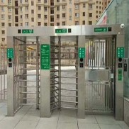
 Double Lane Full Height Turnstile Gate for Residential Area
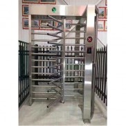
 Dual Lane Tandem Full Height Turnstile Gate for Industry Park
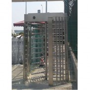
 Single Full Height Security Turnstile for Office Buildings
 Motorised Double Full-Height Turnstile for Office Buildings
Please leave a message if you are interested in this model