What is an entry turnstile?
The general description of an entry turnstile
It relates to an entry turnstile and more particularly to a turnstile access control that is controllable in either of two directions.
It is concerned primarily with controlling the entrance and exit to a rapid transportation system where passengers have the capability of purchasing prepaid tickets to a plurality of different destinations. The entry turnstile is made to respond to logic means which interrogates the ticket and the determines the validity of the ticket in order to meter the passage of the passenger into the systems. Similarly the ticket must again be interrogated to determine the validity of the ticket as actually used by the passenger, by comparing the point of departure of the customer and the kind of ticket being presented. Should the logic associated with the turn style door determine that the ticket is valid for the trip actually made, the turnstile mechanism will be impulsed to allow the passenger to exit from the transportation system.
lt can be appreciated therefore that the turnstile mechanism must be capable of allowing passage in either of two directions independently and under separate control.
In the prior art turnstile mechanisms have achieved control in a given direction only. Rotation inthe opposite direction was usually not a requirement since most prior art systems were limited to a fixed charge for use of the complete transportation system and hence, it was only necessary to meter access to the system and allow free exit. In such systems, a simple ratchet or spring loaded keeper device would be sufficient to allow free exit through the same optical turnstile.
The modem turnstile operating with prepaid tickets having a plurality of traveling options is expected to operate in unattended areas. The turnstile equipment must maintain positive control. In addition it is necessary for safety purposes that in the event of an emergency or power failure that the turnstile become free wheeling in both direction.
It describes a simple, fool-proof mechanical turnstile that is separately controllable in either direction and is securely locked when not in use so as to present movement of the entrance turnstile without the insertion of a proper valid ticket. In the event of a fire occasioned by a power loss the turnstyle door becomes automatically free wheeling in either direction thereby allowing passengers to exit from the system and also to allow emergency personnel to immediately enter the system whenever their services are required.
It is described a rotatable shaft having a cog tooth wheel assembly on one side and a plurality of spaced apart tubes for passenger control on the other side. In the conventional configuration three tubes are used for a complete revolution to thereby meter the passage of three passengers for one revolution of the shaft. A first push pawl has a leading edge for contacting one edge of a single cog to present rotation of the shaft in a countercloekwise direction and a cammable trailing edge adapted to be cammed by the cogs should the shaft be rotated in a clockwise direction. Similarly a separate pull pawl has a leading edge for contacting the other side of a single cog so as to prevent clockwise rotation of the shaft and a cammable trailing edge adapted to be cammed out of positiön by the cogs should the shaft be rotated in a counterclockwise direction.
Both pawls are individually controlled by separate solenoids that hold each pawl in a detented position against a spring action to thereby lock the shaft from rotating in either direction. A signal indicating an allowable clockwise rotation of the shaft will result in the solenoid controlling the pull pawl to be de-energized thereby allowingthe pull pawl to be raised by the spring action which allows the shaft to rotate one-third of a revolution. A rotating cam operated upon by the cog assembly closes a switch which applies full power to the solenoid causing it to fully detent and lock the cog wheel from moving. The fully detented position of the pawl is detected by a second switch which removes full power from the solenoid and applies only half power which is all that is necessary to maintain either pawl in a locked position. It has been recognized that the power necessary to fully detent a pawl is greater than the power necessary to maintain the pawl in a detented position.
Similarly should the logic equipment associated with the gate control indicate that a proper counterclockwise rotation of the cog wheel is desired then the solenoid holding the push pawl will be de-energized allowing the biasing spring to raise the push pawl from the cogs. Passenger rotating of the anti-tailgating turnstile device will rotate the shaft and the cog wheel. One-third of a revolution later a second cam will close and an associated switch will apply full power tothe solenoid controlling the push pawl which will fully detent the push pawl and lock the cog wheel against rotation in either direction.
As mentioned previously seating of the push pawl will close a second switch which will remove full power and maintain a half power condition for holding the pawls in a detented position awaiting the next action by a passenger.
The cog wheel has three bearings located on one side of the cog wheel for defining an equalateral triangle. A generally U-shaped homing device controlled by a spring loaded riser arm is used to provide a stiff action to the entry turnstile mechanism. Movement of the access entrance gate turnstile and the cog wheel will cause the bearing members to rotate causing the homing device to move in an up and down direction against the action of the spring loaded riser arm. Movement ofthe riser arm causes the shaft containing the cams to rotate which in turn controls the switches for applying full power tothe individual solenoids.
The detailed description of an entry turnstile
Further objects and advantages will be made more apparent by referring now to the accompanying drawings wherein:
FIG.1 is a side view of the emtry turnstile mechanism constructed in accordance with the teachings
FIG.2 is a rear view illustrating the cog wheel assembly shown in FIG.1;
FIG.3 illustrates the timing position between the cog teeth and the cams; and
FIG.4 illustrates the application of full power fordetenting the pawls.
Referring now to FIG.1 there is shown a triangulated hub assembly 10 mounted on a shaft 12 for holding a plurality of entry turnstile tubes 14 adapted to meter the passage of passengers through a suitable gate opening. Upon the presentation of valid ticket the biometric turnstile mechanism is enabled thereby allowing the exertion of pressure on any tube 14 to rotate the hub 10 resulting in a rotation of shaft 12.
Mounted on a side opposite the hub 10 is a cog wheel 16 having a plurality of cogs 18 located on the periphery thereof. In the preferred embodiment the number of cogs is a multiple of the number of passenger tubes 14 located in the hub 10. In the present embodiment there are 15 cogs thereby allowihg the passage of five cogs for each one-third rotation of the shaft 12 which is indicative of the passage of one passenger through the barrier arm optical turnstile.
The individual cogs 18 have sides 20 and 22 that are preferrably at an angle to the land portion 24 which angle is less than 90°. The sides 20 and 22 of each of the cogs 18 could be vertical, however, experience has shown that the security of the turnstile mechanism is immeasurably increased by having a slight angle that is less than 90°.
Located on one side of the rotating cogwheel 16 is a shaft 26 for holding a first pull pawl 28 and a push pawl 30. Both the push pawl 30 and the pull pawl 28 are free to rotate about shaft 26 and are not otherwise attached to the shaft. Each of the pawls 28 and 30 is spring loaded in a normally disengaged position as shown in
FIG.2 by means of a pair of springs 31 and a second spring ( not shown). Clearance between the individual pawls 28 and 30 and the cogwheel teeth 18 is provided by means of adjusting screws 33 and 34 located on each of the pawls.A pair of normally closed switches 35 and one not shown, one for each pawl 28 and 30, is controlled and operated by a pair of screws 37 and 38 located on each pawl for opening normally closed switches 35 and 36 respectively whenever the individual pawl is completely detented in the cogwheel assembly. The function of switches 35 and 36 is to disconnect the full power applied to the solenoids after the pawls have been fully detented. This function will be described in more detail in connection with FIG.4.
Pawl 28 is controlled by a solenoid 40 in such a manner that energising the solenoid pulls lever 42 which is attached to the pawl 28 thereby causing the pawl to rotate about the shaft 26 and contact the cogwheel assembly 16.
In a similar manner, solenoid 44, when energized will pull linkage 46 attached to the push pawl 30 thereby causing the pawl to rotate about shaft 26 and contact the cogwheel assembly 16. The operating end of the pull pawl 28 is shuped inthe form of a hook having a leading edge 50 adapted to contact the edge 20 of a cog 18 so as to prevent clockwise rotation of the cogwheel assembly 16. Opposite the leading edge 50 is a trailing edge 52 having a cammable surface adapted to be contacted by side 22 of the cog 18 so as to cam the pull pawl 28 when the cogwheel assembly 16 is rotated in a counterclockwise direction. It can be appreciated therefore that the pull pawl 28 when energized will therefore prevent clockwise rotation of the cogwheel assembly 16, but will otherwise not interfere with counterclockwise rotation since the pull pawl 28 will be cammed outof position during the counterclockwise rotation.
A review of the push pawl 30 will show a leading edge 54 adapted to contact edge 22 on a cog 18. With the push pawl in a detented position the leading edge 54 will contact edge 22 of cog 18 and prevent counterclockwise rotation of the cogwheel assembly 16. On the side opposite the leading edge 54 on the push pawl 30 is a trailing edge 56 having a cammable surface adapted to be cammed by the surface 20 of a cog 18 when the push pawl 30 is in a detented position. Hence, with the push pawl 30 detented the cogwheel assembly is prevented from rotating in a counterclockwise direction but is free to rotate in a clockwise direction.
The operating mode for the entry turnstile assembly is for both solenoids 40 and 44 to be energized thereby causing the pull pawl 28 and the push pawl 30 to be fully detented. In this position clockwise rotation of the cog wheel assembly 16 is prevented by means of the contacting of the leading edge 50 on the pull pawl against edge 20 of the cog 18. Counterclockwise rotation of the cog wheel assembly is prevented by the leading edge 54 ofthe push pawl 30 contacting the edge 22 of the cog tooth 18. Since the push pawl 38 and the pull pawl 28 are side by side, the operating surfaces could work on the same tooth segment or in adjoining segments as illustrated in FIG.2. As will be explained in connection with FIG.4, full power is only applied to solenoids 40 and 44 during the initial detenting of the pawls 28 and 30 and, once detented, only half power is applied to hold them in the detented position.
The operation of the motorised optical turnstile gate is restrained against a free-wheeling action when in the operating mode by means of three equally spaced rollers 68, 62, and 64 located on the side of the cog wheel assembly 16.The number of rollers is determined by the number of turnstile tubes 14 located in the hub 10. A homing device 66 shaped in the general form of a U is adapted to contact two of the rollers at any given time as the cog wheel assembly 16 is rotated. The homing device 66 is centrally supported bya riser arm 68 pivoted at one point on shaft 26 and at the other point on shaft 70 that is fixedly attached to the central position of the homing device 66. A compression spring 72 is wrapped around the shaft 26 and contacts shaft 70 on the riser arm 66 so as to continuously urge the homing device in a downward position to thereby restrain the movement of the entry turnstile assembly when actuated by a passenger. In other words, the passenger pushing on the passenger tube 14 will rotate the hub 10 and thereby rotate the cog wheel assembly 16 against the action of the spring 72 so as to prevent free-wheeling of the high security turnstile which in a proper operating mode.
In the preferred embodiment a damper arm 76 connected to a suitable dash pot or damper assembly (not shown) has a bearing wheel 78 adapted to contact the lower end of one of the U-shaped extensions of the homing device 66 to thereby provide an additional restraint on the rotation of the cog wheel assembly 16. The purpose of the damper assembly is to prevent a passenger from pushing on the entry turnstile tube 14 in a fast and sudden movement that could either injure himself or possibly injure the passenger ahead or in back of him.
The shaft 26 not only supports the riser arm 68, but is attached to the riser arm so that movement of the riser arm in a vertical up and down direction as controlled by the rotation of the cog wheel assembly 16 will cause the shaft 26 to rotate. Located on the shaft 26 and attached to the shaft is a pair of cams 80 and 82 that are adapted to contact and control a pair of switches 84 and 86, respectively.
Referring now to FIG.3, there is shown a preferred relationship between the pawl 28 and a tooth 18 on the cog wheel assembly 16 for adjusting the cam 82 to close.switch 86 used to apply full power to the solenoid 40. The position shown in FIG.3 represents the positions of the cog tooth 18 after a passenger has been properly admitted and the cog wheel assembly has rotated five cog teeth. The riser arm 68 is moved in a vertical direction once for every five cog teeth, which rotates shaft 26 and cams 80 and 82.
Cam 82 is adjusted to close and contact the switch 86 at the time that the leading edge 50 is centrally located on the fifth cog tooth 18 at Which time the cam 82 will close switch 86 as shown in FIG.4 to thereby apply full power from a suitable power supply 90 through the normally open contacts 86 and through the normally closed contacts of switch 36 to the solenoid 40. Subsequent rotation of the cog wheel assembly 16 by the passenger will result in the pull pawl 28 being pulled down with full power into the fully detented position to thereby prevent further clockwise rotation of the cog wheel assembly 16 since the leading edge 50 will now be contacting the edge 20 of thecog tooth 18. At the time that the pawl 28 is fully detented, the normally closed switch 35 is opened by means of adjusting arm 37 for removing full power from the solenoid 40. The solenoid 40 will continue to receive half power which is sufficient to maintain the pawl 28 in a closed position.
The adjustment for the push pawl 30 is the same as just illustrated in connection with FIG.3, only in this case cam 80 is adjusted to close switch 84 which will then apply full power from the power supply through the normally open contact of switch 84 and through the normally closed contacts of switch 36 to the solenoid 44. The full detenting of the pawl 30 will cause switch 36 to be opened thereby applying half power to the solenoid 44 during the holding operation.
It can be appreciated, therefore, that the electronic security turnstile device just described is capable of individually metering passage in either direction ina safe and reliable manner. In addition, should an emergency develop and power be lost from the system, then the operation of spring 31 and the one not shown will immediately cause pawls 28 and 30 to be lifted from their detented position to allow the turnstile to be rotated in either direction without restriction.
Claims
1. An entry turnstile for allowing metered movement in either direction comprising: a rotatable shaft having a toothed wheel on one side and a plurality of spaced-apart tubes for passenger control on the other side, each of said teeth having a first edge and a second edge; a first pawl havinga leading edge contacting said first edge for preventing clockwise rotation of said shaft, said first pawl having a trailing edge cammable by said teeth in the presence of counterclockwise rotation of said shaft; a second pawl having a leading edge contacting said second edge for preventing counterclockwise rotation of said shaft, said second pawl having a trailing edge cammable by a power serving means including first cam means for sensing the position of said first pawl in an undetented position and applying full power to said first solenoid and limit switch means for detecting detenting of said first pawl and reducing the power to said first solenoid.
2. An entry turnstile system according to claim 1 further including second cam means for sensing the position of said second pawl inan undetented position and applying full power to said second solenoid, and limit switch means for detecting detenting of said second pawl and reducing the power to said second solenoid.


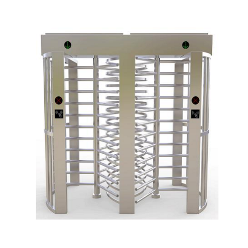
 Double Lane Full Height Turnstile Gate for Residential Area
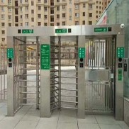 Dual Lane Tandem Full Height Turnstile Gate for Industry Park
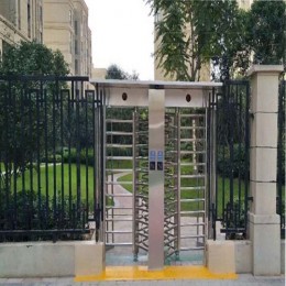
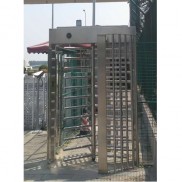
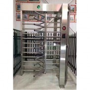 Single Full Height Security Turnstile for Office Buildings
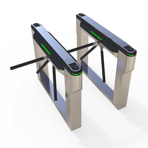
 Motorised Double Full-Height Turnstile for Office Buildings
Please leave a message if you are interested in this model