The reliable traffic control solution– automatic vehicle barrier
What is an automatic vehicle barrier?
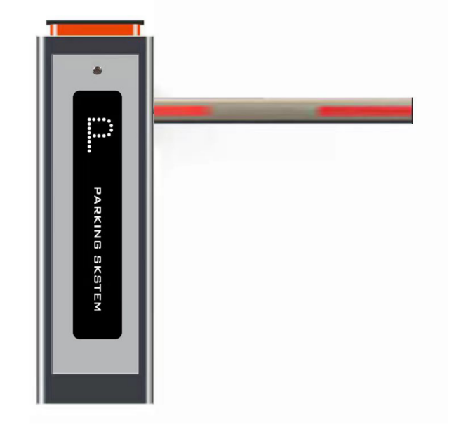
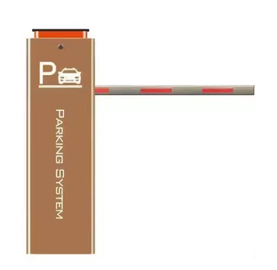
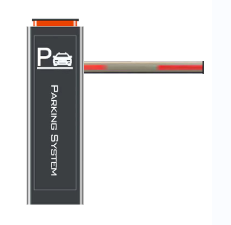
What we discussed here relates to an automatic vehicle barrier coming with a barrier column and a barrier boom, whereby the barrier boom can be swiveled on one side of the barrier column is arranged in an orderly manner and has no supports on the other end, whereby the barrier column is used to arrange the barrier arm pivoted about a horizontal axis bare barrier boom mount, as well as with a a motor drive for the barrier boom and one that interacts with the motor drive control device.
Vehicle barrier gate has a barrier pillar and a barrier boom. The barrier boom can be pivoted about a horizontal axis barrier column arranged and can consist of a closed position to an open position and vice versa be proceeded. The barrier boom is in a closed position, usually in a horizontal position. Located in the open position, the barrier boom is usually vertical position, that is in the direction of gravity aligned.
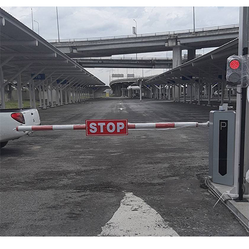
Automatic vehicle barrier gate described above can be found, for example, at entrances and exits from parking lots clearence, as barriers to customs or toll systems men or at railway crossings., etc.
The structurer of an automatic vehicle barrier?
For arranging the barrier boom on the the barrier column serving as a barrier boom holder. This is provided by the barrier column, and it can be pivoted about a horizontal axis educated. When fully assembled, the hinge takes the barrier boom on one side, that is, at one end, on. On the other end, the barrier boom is free of supports trained, which means there is no support for the cabinet provided, which is in the closed position of the barrier boom of the structural support of the the end of the barrier boom away from the column. The end of the barrier boom furthest from the column is perhaps more free-floating.
For proper pivoting, the barrier boom is powered by a motor drive. There is an electric motor, which is usually used as a syn-chronmotor is designed, and an electric motor downstream transmission. It is also a rule a safety clutch is provided, which is on the output side tig of the gearbox, i.e. connected downstream of the gearbox between the gearbox and the barrier boom mount, is arranged. The barrier boom is between one vertical open position and a horizontal position closed position moved by the motor drive, whereby the motor drive also serves to barrier boom in the horizontal closed position position in suspension so that there is no disturbance.
Reaching the end positions of the barrier boom, that is, reaching the horizontal closed position on the one hand and the opening reach the vertical open position on the other hand is detected using appropriate position sensors, which is on the motor shaft of the motor drive means on the transmission input side, or on the drive shaft the barrier boom holder, i.e. gearbox on the aisle side. The position sensors are micro switches, rotary value switches encoders or Hall sensors.
The signals detected by such position sensors. The measured values are sent to control electronics. Guided which follows the movement sequence according to the achievement the desired end position is completed, in- corresponding to that of the motor of the motor drive is regulated.
The ones that are usually present on the transmission output side. The clutch seen is a torque-switching system. Safety clutch designed to ensure that due to forces acting on the barrier boom large torques are transferred to the motor drive be led. This can be caused, for example, by obstacles caused in the travel path of the barrier boom. but also through vandalism. Typically is the clutch as a non-positive slip clutch or designed as a positive locking body coupling and slips when overloaded or bends at an angle according to which between adjacent form-fitting elements trained.
Although there are limitations to the above-described. This type has proven itself in everyday practical use. there is still a need for improvement. In particular, it will particularly viewed as disadvantageous is that in the case of an initial installation of the barrier requires adjustment. So the end position positions are determined by mechanical measurement lungs of the barrier boom and it is the connection between the end positions determined in this way positions and those recorded by the position providers to produce the desired values. This regulation represents one additional effort when installing the automated vehicle barrier system. Furthermore, this regulation is lost if it as a result of an impact on the barrier boom overload causes the safety clutch to slip. It is therefore based on the previous description, a vehicle boom barrier is consistent to propose a structure that simplifies handling exercise is permitted, especially during initial assembly. To solve this problem, a vehicle barrier gate system mentioned at the beginning is presented which are characterized by the characteristic features of claim 5.
The solution takes place a positioning device known from the prior art encoder specifies a measuring unit that provides a measuring device for storage recognition, in the form of a corresponding gyrometric sensor, preferably in conjunction with a win- sensor. Such a measuring device is used in the difference to a previously known position provider, to determine the absolute position of the barrier boom in the room grasp. So it becomes a departure from the state of the art not the relative position of the barrier boom opposite detected by a motor or drive shaft. The measuring device Rather, it serves to determine the angle of inclination between the Barrier tree and the direction of gravity to grasp, therefore the absolute position of the barrier boom in space.
This configuration has the advantage that regulation also during initial assembly or if the barrier is not required. Because of measurement technology no longer the relative position of the barrier boom detected relative to a motor and/or drive shaft no adjustment or adjustment is required. regulation, as in the manner described above constructions known to the prior art the case is. In addition, the one described above is also disadvantage eliminated that as a result of an overload conditional triggering of the safety clutch of a new The barrier regulation needs to be adjusted. A certain correct operation of the barrier remains unwarranted even after an overload. interruption possible.
The construction proves this makes it much easier to handle overall. ownership, both with regard to initial use commissioning as well as when re-commissioning following an overload accident.
The measuring device is according to another featur on the barrier boom or on arranged in the barrier boom mount. In case of a appropriate pivoting movement of the The measuring device therefore covers the barrier tree same pivoting angle as the barrier boom itself, so that the inclination of the barrier boom, that is, the orientation of the barrier boom is relative opposite the direction of gravity and/or the barrier column, can be recorded as a measurement variable can. The desired end position positions of the cabinet can be done precisely and without any calibration process be controlled. The control device delivers A comparison circuit is available for this purpose recurring comparison between predetermined ren target values on the one hand and measured actual values permitted.
The control device can also be designed in such a way that in the event of accidental or misuse overload in the direction of rotation of the barrier boom Overload initially gave way and when there was no overload and/or elimination of the overload of the barrier boom as- which is moved to the desired end position. This ensures that even after a trigger the safety coupling of the barrier boom into its position desired end position is moved as soon as the triggering obstacle is removed.
According to a further feature, it can be provided that the motor steps of the motor evaluate the motor belonging to the relevant drive and these against the signals supplied by the measuring device check plausibility. If the measured and the calculated waited change in position of the barrier boom is not exceeded agree, this indicates a possible defect in the barrier and a corresponding error may occur. message sent to a remote monitoring system become.
We propose a control device for the operation of a vehicle barrier system, with a barrier column and a pivotable one on the Barrier boom arranged on the barrier column, which is a a measuring unit with a measuring device for absolute measurement detection and a comparison circuit occurs, which are characterized by the characteristic features of the Proverb 1 distinguishes. Such a control device This is achieved using the method according to the invention Barrier described advantages.
We also propose a method for operating an electric vehicle barrier with a barrier column, a arranged on the barrier column so that it can be swiveled. the barrier boom and a motor drive for the barrier boom, using a measuring unit with a measuring device for absolute position detection has a gyrometric sensor of the tilt angle kel between the barrier boom and the effective direction of the Gravity and/or the barrier boom and the screw column recorded and the angle of inclination corresponding actual signal to a comparison circuit is carried out, in which the comparison circuit is used to this actual signal is compared with a predeterminable target value. chen, whereby in the event of an inequality of actual gnal and target value a corresponding control of the motor drive for the barrier boom will lead.
In terms of procedure, it is provided that by means of a measuring unit of the inclination angle between the barrier boom and the direction of gravity is recorded. For this purpose, in the already existing a gyrometric measuring device in the manner described for use on the barrier boom itself or on the Barrier boom holder of the barrier column attached is ordered. This measuring device is a a sensor that is used in normal operation. The electro-mechanical vehicle barrier covers the same angle as the one barrier boom. This angle is determined by measurement grasps and sets the angle of inclination between the barrier tree and the direction of gravity.
The measurement unit records one actual signal corresponding to the inclination angle is generated and fed to a comparison circuit. Here you will find a equal between the actual signal, i.e. the measurement signal, on the one hand, and a predeterminable setpoint on the other. On the other hand, the target values are preferred- show the possible end position positions of the lock kenbaums is used, which means, for example, 90° for the vertical open position and 0° for the horizontal closed position of the barrier boom. In the course of carrying out the method which has already been explained above. The advantages explained above the limit.
The detailed description of an automatic vehicle barrier?
Further features and advantages can be seen from the following description:
Fig.1 is a schematic representation appropriate barrier and
Fig.2 is a schematic representation proper implementation of the procedure.
Fig.1 shows a schematic representation recognize barrier 14. This has in a manner known as a barrier column 1 and a barrier boom 5, the latter being the better for the sake of clarity.
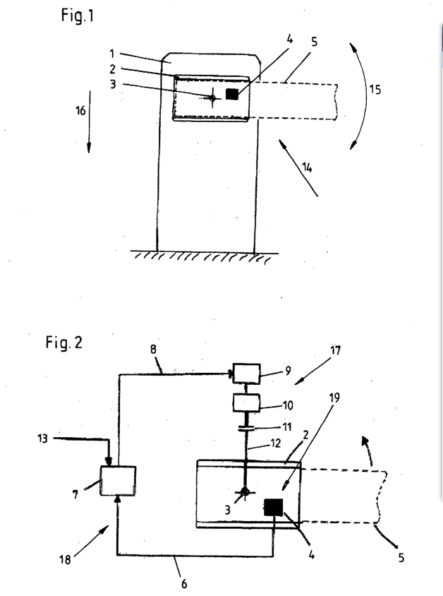
The barrier column 1 represents a barrier tree recording 2 ready. This is about a horizontal one Axis 3 can be pivoted so that the barrier boom 5 in the final assembled state a pivoting movement can complete in the pivoting direction 15. Fig.1 shows the barrier 14 is closed position of the barrier boom 5.
To pivot the barrier boom 5 serves a motor not shown in detail in Fig.1 Drive 17. This has an electric motor 9, a Gearbox 10 and one provided on the gearbox output side hene safety clutch 11, which acts as a slip clutch is designed and transmits force between the device drives 10 and a drive shaft 12 for the barrier tree 5 is arranged.
The barrier 14 also has one control device 18. This is with a comparison circuit 7 and a measuring unit 19 equipped has a gyrometric measuring device 4, which in general shown embodiment on the barrier boom mount me 2 is arranged.
When used as intended pivots what is designed, for example, as a sensor gyrometric measuring equipment 4 together with the cabinet kenbaum 5, along with this, paints over the identical angle between barrier boom 5 one on the one hand and the effective direction 16 of gravity on the other. In this way, the absolute position of the cabinet can be kenbaums 5 can be determined in space.
Fig.2 shows a schematic representation of the resulting recognize that the process is being carried out.
The intended use case from the gyrometric measuring device 4 supplied actual gnale 6 are considered the angle of inclination between Barrier boom 5 and direction of gravity 16 corresponding measurement signal from a comparison circuit 7 supplied. There is a comparison between the actual Signals 6 and predeterminable target values 13 instead. In from- depending on the comparison result, a control system is signal 8 for the motor 9 of the motor drive 17 so that a corresponding motor control takes place. The motor 9 rotates according to the received request control signals 8 via the gearbox 10, the clutch 11 and the drive shaft 12 the barrier boom holder 2 and thus also the barrier it accommodates kenbaum 5. The resulting change in position of the Barrier tree 5 is again from the gyrometric measuring device 4 is recorded and again presented as the actual signal 6 the comparison circuit 7 of the control device 18 given, so that through the continuous process of measuring and tracking the barrier boom 5 closed control loop through which the switch kenbaum 5 ultimately achieves the desired end position positions according to the target values 13.
Claims
1. A control system for operating a vehicle barrier gate system (14), in particular a vehicle barrier, comprising a barrier column(1) and a barrier boom (5) which is arranged in aswiveling manner on the barrier column (1), wherein the control system comprises a measuring unit (19) having a measuring device (4) for the absolute position detection of the barrier boom and a comparator circuit (7), characterized in that the measuring device (4) for the absolute position detection comprises a gyrometric sensor.
2. A control system according to claim 1, characterized in that the measuring device (4) for the positiondetection is arranged on the barrier boom (5) or ona barrier boom receiver (2) provided by the barrier column (1).
3. A control system according to claim 1 or 2, characterized in that the measuring unit (19) serves to detect the inclination angle between the barrier boom(5) and the effective direction (16) of the gravity.
4. A control system according to claim 1, 2 or 3, characterized in that the measuring unit (19) serves todetect the inclination angle between the barrier boom(5) and the barrier column (1).
5. A vehicle barrier system, comprisinga barrier column (1) and a barrier boom (5), whereinthe one end of the barrier boom (5) is arranged on the barrier column (1) in a swiveling manner and the other end has got no support, wherein the barrier column (1) provides a barrier boom receiver (2), which can be swiveled around a horizontal axis, for the arrangement of the barrier boom (5), as well as comprising a motor drive (17) for the barrier boom (5) and a control system (18) which cooperates with the motor drive (17), characterized in that the control system comprises the features of one of the preceding claims 1 through 4.
6. An automatic road barrier system according to claim 5, characterized in thatthe measuring device (4) is arranged on the barrierboom (5) or on the barrier boom receiver (2).
7. A car parking barrier according to claim 5 or 6, characterizedin that the control system (18) provides a comparator circuit (7).
8. A method for operating a barrier (14), in particular avehicle barriergate, comprising a barrier column (1), a barrier boom (5) which is arranged in a swiveling manner on the barrier column (1) and a motor drive (17) for the barrier boom (5), in which method the inclination angle between the barrier boom (5) and the effective direction (16) of the gravity and/or between the barrier boom (5) and the barrier column (1) is detected by means of a measuring unit comprising a measuring device (4) for the absolute position detection (19) comprising a gyrometric sensor and an actual signal (6) corresponding to the inclination angle is transmitted to a comparator circuit (7), wherein this actual signal (6) is compared to a pre-determinable nominal value (13) by means of the comparator circuit (7), wherein in the case of inequality of the actual signal (6) and the nominal value (13) a corresponding triggering of the motor drive (17) of the barrier boom (5) will take place.
9. A method according to claim 8, characterized inthat end positions of the barrier boom (5) are usedas nominal values (13).


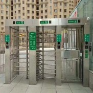
 Double Lane Full Height Turnstile Gate for Residential Area
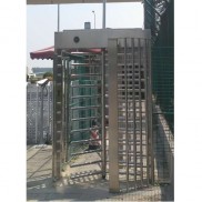
 Dual Lane Tandem Full Height Turnstile Gate for Industry Park
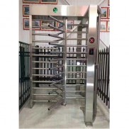 Single Full Height Security Turnstile for Office Buildings
 Motorised Double Full-Height Turnstile for Office Buildings
Please leave a message if you are interested in this model