Add: Room 501, No.6, West 4th Alley, XingWei Village, FuYong Town, BaoAn District, Shenzhen, China
E-mail: luke@jaydagate.com
Wechat: Lukerong2013
Whatsapp: +86-13548106515
Mobile: +86-13548106515
Skype: jaydagates@outlook.com
Barrier gates, well known as car park barriers or automatic vehicle barriers, are ideal traffic control solutions that can be used as automatic traffic barriers for car parks and security control. The automatic barrier gates have quick opening times, low operating costs, easy handling, great reliability, and a long lifespan as effective parking applications. They are frequently used in car parks, hotels, commercial complexes, hospitals, shopping centers, toll booths, and other application areas. Additionally, they are available with an extensive range of arm lengths ranging from 2 to 6 meters and different arm types, including straight/articulated/fence boom.
To achieve a smooth elevation or lowering of the barrier arm and prevent bounce in the end position, automatic gate barriers are equipped with an updated digital DC24V brushless motor that incorporates a planetary gearing system with a sinusoidal movement. They are always used in conjunction with a safety loop detector wiring system to detect vehicles. This system is installed under the gate arm to prevent the gate arm from unintentionally closing on a vehicle. Our automatic barrier arm gates offer speeds that can be adjusted directly from 0.6 to 6 seconds. Typically, each boom length is set to a standard operating speed.
With their thin profiles and indoor and outdoor usage designs, barrier gate arms are ideal for tight spaces and high-volume applications. Such security barrier gates are also used to guard car parks, entrances, restricted areas, checkpoints, or any other type of exit/entry point, controlling traffic in both directions, and they offer a quick, dependable, smooth operational way with little noise and power consumption.
As a reputable barrier gate system supplier and manufacturer with strong manufacturing and R & D capabilities, our company offers a range of automatic parking barriers with various designs and prices. We also continuously introduce new products for customers around the world each year, and we can also customize barrier gate systems to meet specific client needs. Please get in touch with us for additional information.


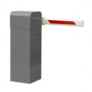
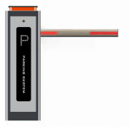 Affordable Electtric Security Barrier Gate JDDZ-13
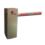
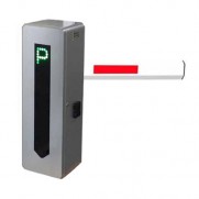 DC24V Brushless Motor Car Park Barrier JDDZ-10
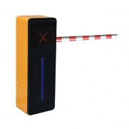
 0.6~6 Seconds Variable Parking Barrier Gate JDDZ-7
 Automatic Rising Arm Barrier JDDZ-11
 Powder Coating Automatic Arm Barrier JDDZ-9