The applications of the turnstile security system
The Technical Problem
At workplace premises, such as factories or construction sites, there is a requirement to identify personnel, who are on the premises. This information has typically been obtained by requiring employees to clock on and off when entering and leaving the workplace. Such turnstile security systems use tokens that can easily be transferred between workers. One worker may also clock on for several. There is therefore a well established problem of time and attendance fraud.
It is also frequently necessary to provide secure access systems to ensure that only authorised personnel enter a premises. This is a requirement for high security risk areas such as cash centres.
This is concerned with the technical problem of identifying personnel as they enter or leave a premises through a secure barrier and providing output data to enable the duration of their presence on the premises to be recorded.
The existing solutions of turnstile security system
Full height security turnstiles are often used to control access to premises, such as sports stadiam and stations where tickets are checked at the entry point. A turnstile is an effective system for ensuring that only one person enters the premises at a time as it can be released for limited rotation in response to a check made on a ticket.
Typically full-height turnstile gates have three 120 degree rotor sections. Such systems allow entry when released. However if the turnstyle gate release mechanism is operated by checking a token, it is possible for someone other than the person presenting the token to enter when the turnstile door is released. By using a four 90 degree sector turnstile, there is a secure position between entry and exit where verification can take place. Such “mantrap” turnstile barries are often used at sports stadiam to enable entrants to be processed one at a time by an operative who has a booth giving access to the sector between entry and exit. The operative can release the turnstile for rotation either way enabling the entrant to move into or leave the premises.
We provide such a mantrap security turnstile with an electric control system for locking and release of the turnstile. A Jayda turnstile has been described in which an independent two stage entry process of the mantrap turnstile requires an initial access control device (generally a card reader) to allow the first 90 degrees of rotation. At this point, the user may reverse out of the turnstile (freely if a free exit or via a push button if a controlled exit) or continue to proceed with an entry cycle. If a complete entry is desired, then a second access control device (generally a biometric unit) is used to allow the final 90 degree cycle to complete the total entry process. The benefit of this independent two-stage system is that it requires a sequential use of the first, then second, access control device to complete an entry cycle. Since there are two independent locking and electrical control mechanisms for each stage, it is impossible to use the first, generally non secure, reader twice consecutively to gain entry. Otherwise, the user would bypass the security of the biometric reader.
The relevance of biometrics to the identification of personnel for security purposes has been appreciated. Finger, hand, facial and retinal biometric templates can be stored and matched with data measured at a point of entry. This arrangement does not solve the problem of ensuring that only the identified person actually enters the turnstile, whereas the Tomsed arrangement would.
For a biometric identification system to be suitable for an industrial workplace, it must be robust, reliable and rapid.
The Solution of our turnstile security system
Jayda provides a security access entry channel unit adapted to be positioned as part of a secure perimeter, the unit having spaced walls defining an entrance aperture and an exit aperture on opposite sides of the perimeter; a turnstile security barrier positioned between the apertures to control passage there between, the morden turnstile having a rotor assembly of four rotor posts each made up of spaced metal arms projecting from a central rotatably mounted shaft, the posts defining four quadrants wherein alternate quadrants are closed off, and at least two fixed barrier posts made up of spaced metal arms projecting from the wall alongside the respective apertures and through which barrier posts the rotor posts rotate;a camera mounted in a housing aligned with the secure perimeter and positioned to produce an image of a person held within an open quadrant between the apertures; and a control unit for processing the image against a biometric template of pre-stored characteristic dimensions relating to selected persons in order to identify the person and control operation of the entry turnstile in response to the identification.
Alternate quadrants of the electronic turnstile are closed off in order to prevent “piggy-back” entrants without the need for a release to enable entry to the turnstile.
Preferably the security access entry channel unit further comprises a clock and means for recording and outputting data relating to specific persons entering and leaving through the channel. A clock preferably records the time of entry and exit of each user and can output data directly to a payroll administration system
The advantages of our turnstile security system
The security access entry channel unit is robust and by using a biometric identification based on a camera image the need for contact with the user is avoided. The users also do not need to carry any keys or cards, which may be lost or be transferred to unauthorised users.
A further advantageous feature is that the camera can record an image of any person that fails to be identified.
The unit mentioned accordingly solves the technical problems of security and payroll data collection in a single operation.
Brief description of the drawings of the turnstile security system
In order to be well understood it will now be described, by way of example only, with reference to the accompanying diagrammatic drawings, in which:
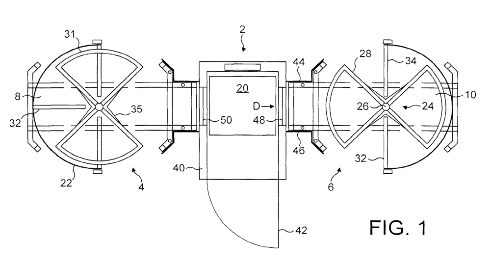
Figure1 shows a top plan view of a security access entry channel unit;
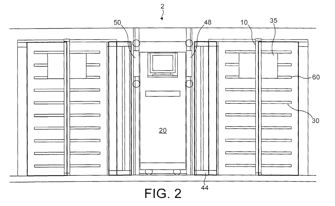
Figure 2 shows a section through the unit of Figure 1 ; and
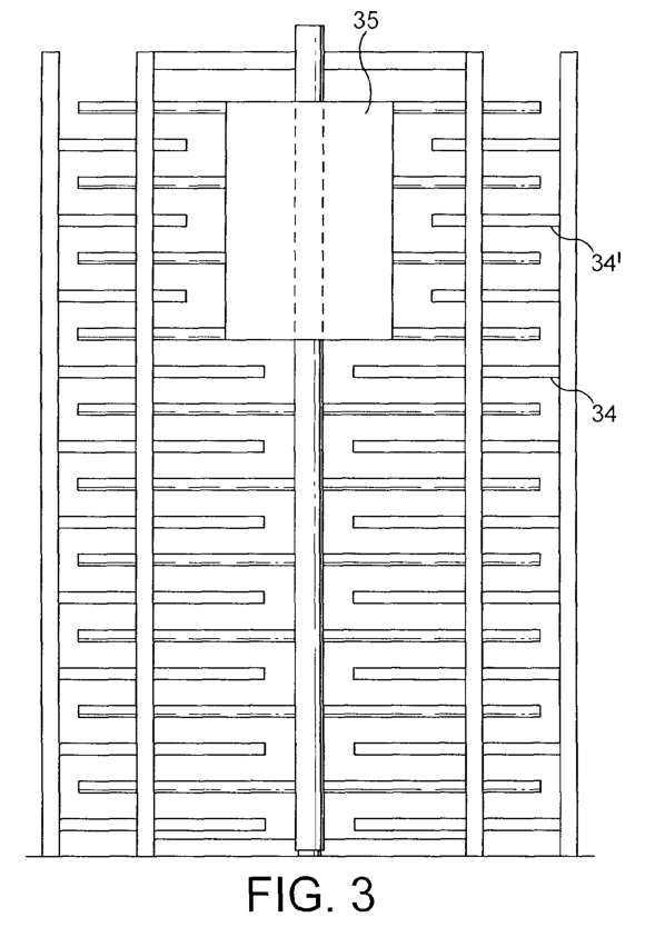
Figure 3 shows a view in the direction of arrow A in Figure1
The overview of the turnstile security system
A security access entry channel unit 2 as shown in Figures 1 and 2 has two separate access channels 4, 6 each controlled by an independent bi-directional turnstile 8, 10, which are separated by a control cabin 20.
The unit is intended to be part of a secure perimeter of, for example, a construction site. However, it will be appreciated that the unit may equally be used to control entry and exit from any secure area.
The unit 2 has spaced walls 22 made of steel plate screens, which continues the secure perimeter. The walls 22 are onIy interrupted by apertures that provide entry and exit points for the channels 4, 6. Preferably each floor-to-ceiling turnstile 8, 10 is similar and can be used both as an entry and an exit channel. Two channel units are advantageous in that they can share a single control system and provide fora reasonably high through flow of users.
Full height motorized turnstile
Each motorized turnstile 8, 10 is a “mantrap” turnstile and has a rotor assembly 24 consisting of a central, rototably mounted shaft 26 and four rotor posts 28. Each of the rotor posts is made up of spaced metal arms 30.The posts 28 define four quadrants of similar size. The ends of the metal arms 30 are connected to each other by curved metal bars 31, which prevent access to two of the quadrants. This means that only alternate quadrants are available for access by a user. This prevents a second user gaining access by following a first in an adjacent quadrant and thereby “piggy-backing™ on the identification of the first user.
Barrier posts 32 project from opposite ends of a semi circular steel plate screen 22, which forms part of the security perimeter walls of the unit. The barrier posts 32 project towards the central shaft 26. As with the rotor post 26, the barrier posts are made up of spaced, horizontally projecting metal arms34.The arms 34’ in an upper section of the barrier post are shorter than the remainder. The barrier post arms 34 are positioned so that the rotor post arms 30 can rotate between them. The barrier post 32 prevents users entering that part of the turnstile inside the semicircular screen 22.
In an upper section of the two accessible quadrants,a screen 35 is fitted at user head height. This screen 35 is V-shaped and has two wings that project towards the adjacent rotor posts and terminate short of the shortened bars 34’ on the barrier posts. The material of the screen 35 provides a flat, i.e. non-reflective, background against which a clear image of the user’s head and shoulders will stand out. Because of the shortened bars 34′ the screen 35 does not impede rotation of the pedestrian turnstile.
A further barrier post 32 may also be provided opposite the control unit 20 to offer greater security.
Movement of the pedestrian security turnstile is controlled by means of electrical signals generated from the control unit 20, which lock and release the turnstile in a conventional manner.
The Control Unit of the turnstile security system
The control unit 20 is mounted in a cabin 40, accessible by means of a door 42 on the secure side of the perimeter. Since the control unit is also part of the secure perimeter, the cabin is provided with steel plate screens 44,46 on either side of the cabin. The screens 44 on the non-secure side co-operate with the semi circular screens 22 to define entry or exit apertures to the turnstiles 8, 10. Similarly, the screens 46 on the secure side are shaped to define the other sides of the apertures for the channels 4, 6. The screens also exclude excess sunlight from entering the automatic pedestrian turnstile quadrant, and interfering with the functions of the biometric system, which needs a stable and controlled lighting level. The screens 44, 46 are spaced apart on either side of a respective window 48, 50, which allows a camera mounted inside the control unit 20 to have a clear view to a quadrant of the respective turnstile 8, 10 facing the window 48, 50.
The Biometric Identification
The control unit 20 is intended to accommodate the cameras for a biometric identification system. A number of biometric identification systems using cameras are available. For example, many suppliers offer a suitable facial recognition system based on measurement of certain parameters of a face. These parameters are then stored in a template that can be matched with the image of a user captured by the camera. It will be appreciated that the unit of the present invention can be used with various types of biometric unit which rely on camera technology. The unit 2 can also be used to register users for the first time using the same equipment. The camera is positioned directly opposite the screen 35.
The method of operation
The described unit can be used with various different sequences of operation depending upon the security requirements. A person requiring entry through a channel must first enter the mantrap quadrant by pushing on a rotor post 28 and moving into an open quadrant facing the control unit 20. The turnstile rotor may be controlled so that it is only released for rotation through 90 degrees in response to an electronic signal. In this case the user may need to operate an access button mounted on the wall. For greater security, a PIN controlled keyboard could be offered for releasing entry into the mantrap quadrant.
Alternatively theturnstile access control may permit free entry into the mantrap quadrant. In this case a mechanism is needed to activate the biometric identification step. This may be a PIN controlled keypad or a card reader or any other suitable mechanism. An exit button is also provided to enable the turnstile to be released to allow the user to exit the way he entered.
Once in the mantrap quadrant facing the control unit 20, the user is required to face the window 48, 50 with his head and shoulders against the background screen 35.The camera within the control unit is activated by the same control signal that releases the turnstile rotor assembly or a separate activation mechanism. An image of the user is then taken and processed to extract the required measurements to compare with stored templates. If a match is found then a control signal can be sent to the turnstile to release the rotor assembly for rotation through a further 90 degrees in the same sense as the original rotation in order to allow the user to pass through the channel and into the secure area. If no match is found then the signal can be used to rotate the turnstile in the opposition direction returning the user to the same point of entry.
It will be appreciated that various modifications may be made to the control sequence depending on the specific application.
In particular, the camera can record an image of any person who is denied entry.
The control unit includes a clock so that the time can be recorded of each entry. The system can record entry and exit. Since such stand alone time and attendance logging programmes using face recognition are already available, these aspects of the system need not be described in any greater detail.
The use of a turnstile automatic gate to confine a person in a restricted position relative to the window allows such biometric facial identification systems to perform very well as the background is constant. The use of a screen 35 to improve the contrast of the image against the background further improves accuracy and speed of operation and avoids interference with the measurement from the presence of the turnstile bars 30 and 34.
The control cabin can be accessed and the IT equipment used to enable operator intervention in the identification process or when registering new employees.
The claims
1. A security access entry channel unit (2) adapted to be positioned as part ofa secure perimeter, the unit having spaced walls (22) defining an entrance aperture (4, 6) and an exit aperture (4, 6) on opposite sides of the perimeter; a entrance security turnstile (8, 10) positioned between the apertures (4, 6) to control passage there between, the turnstile(8,10) having a rotor assembly (24) of four rotor posts (28) each made up of spaced metal arms (30) projecting from a central rotatably mounted shaft (26), the posts (28) defining four quadrants wherein alternate quadrants are closed off, and at least two fixed barrier posts (32) made up of spaced metal arms projecting from the wall alongside the respective apertures (4, 6) and through which barrier posts (32) the rotor posts (28) rotate; a camera mounted in a housing aligned with the secure perimeter and positioned to produce an image of a person held within an open quadrant between the apertures (4, 6); and a control unit (20) for processing the image against a biometric template of pre-stored characteristic dimensions relating to selected persons in order to identify the person and control operation of the turnstile system (8, 10) in response to the identification.
2. A security access entry channel unit (2) as claimed in claim 1, further comprising a clock and means for recording and outputting data relating to specific persons entering and leaving through the channel.
3. A security access entry channel unit (2) as claimed in claim 1, further comprising a screen (35) at head height behind a person in the quadrant between the apertures (4, 6).


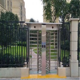


 Double Lane Full Height Turnstile Gate for Residential Area
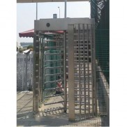
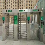 Dual Lane Tandem Full Height Turnstile Gate for Industry Park
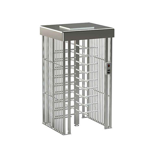
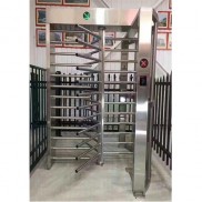 Single Full Height Security Turnstile for Office Buildings
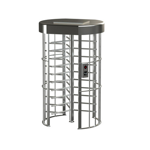
 Motorised Double Full-Height Turnstile for Office Buildings
Please leave a message if you are interested in this model