The turnstile door for access control
What is the turnstile door for access control
The turnstile door is a rotatable device that allows the controlled passage of people, typically one person at a time, through a barrier in order to control access to specific areas. Turn style doors are divided substantially into two macro-categories: turnstyle doors for controlling particularly critical areas (for example full-height and/or impassable turnstiles for stadiums, glass panel turnstiles for subways, turnstile barriers with sliding doors), which must provide high assurances of security, and turnstyle doors for controlling noncritical areas (e.g., offices, swimming pools, sports facilities), which usually have rather compact dimensions. In this second category, turn style doors of the tripod type (or equivalently of the bipod type) and turn style doors with a flap or bar are particularly worthy of mention.
Bidirectional tripod turnstiles allow to prevent the passage of more than one person thanks to the bar that closes behind the user and is furthermore reversible (use in the entry direction and in the opposite exit direction is equivalent). In any case, this type of half height tripod turnstile is relatively bulky due to the rotating structure composed of mutually integral tubes, the outline of which is a cone which necessarily has a greater space occupation than the passage controlled by such outdoor turnstile. Furthermore, this type of drop arm tripod turnstile cannot be used generally as an escape route in case of emergency unless additional mechanisms are used which allow to lower the arms so as to leave the passage clear. Furthermore, this type of automated tripod turnstile has the drawback of preventing the passage of bicycles, pushchairs and the like, since the presence of the bars interferes with their passage.
Flap barrier turnstiles (wherein the flap can be for example a large bar but also a panel) are relatively less bulky than a tripod turnstile gate (since they have a single flap or two mutually synchronized flaps, to the right and to the left of the passage), allow the passage of pushchairs and bicycles and furthermore allow the escape route if the flaps are left in the open position. In any case, closure of the flap, which is motorized, occurs synchronously with a photocell that detects that the user has passed, so that the door closes behind the passing user. The presence of the photocell in this type of flap barrier gate is therefore necessary and generates costs. Furthermore, this flap barrier gate turnstile makes it very difficult, if not impossible, to block the passage of more than one person, since the door must remain open as long as the passage is occupied. Furthermore, the flap turnstile is not easily reversible, i.e., the reverse or exit path cannot be managed in the same manner as entry, due to the absence on the exit side of the apparatuses that are present on the entry side and due to the fact that the flap would move against the user.
Therefore, it is necessary to develop more advanced gate turnstile to overcome the limitations of the background art described above, by providing a turnstile that can be easy and effective to use; providing a turnstile that is compact and allows the passage of users and of any vehicles, such as bicycles or pushchairs, carried by such users; providing a turnstile that can be used as an escape route and allows access control so that users pass one at a time; providing a turnstile that is reversible, i.e., can be used in both of the directions, exit or entry, of the controlled area; providing a turnstile that is able, in an alternative manner, to achieve the advantages of traditional turnstiles, such as tripod or flap turnstiles, eliminating their drawbacks; providing a structure that is simple, relatively easy to provide in practice, safe in use, effective in operation, and of relatively low cost.This aim, as well as these and other objects that will become better apparent hereinafter, are achieved by a turnstile according to claim 1.
The detailed description of the new turnstile door for access control
Further characteristics and advantages of the new turnstile gate will become better apparent from the detailed description that follows, given by way of non-limiting example and accompanied by the corresponding figures, wherein:
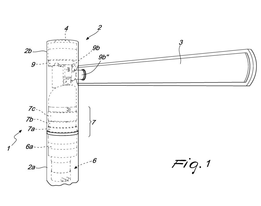
Figure 1 is a front view of the said turnstile door
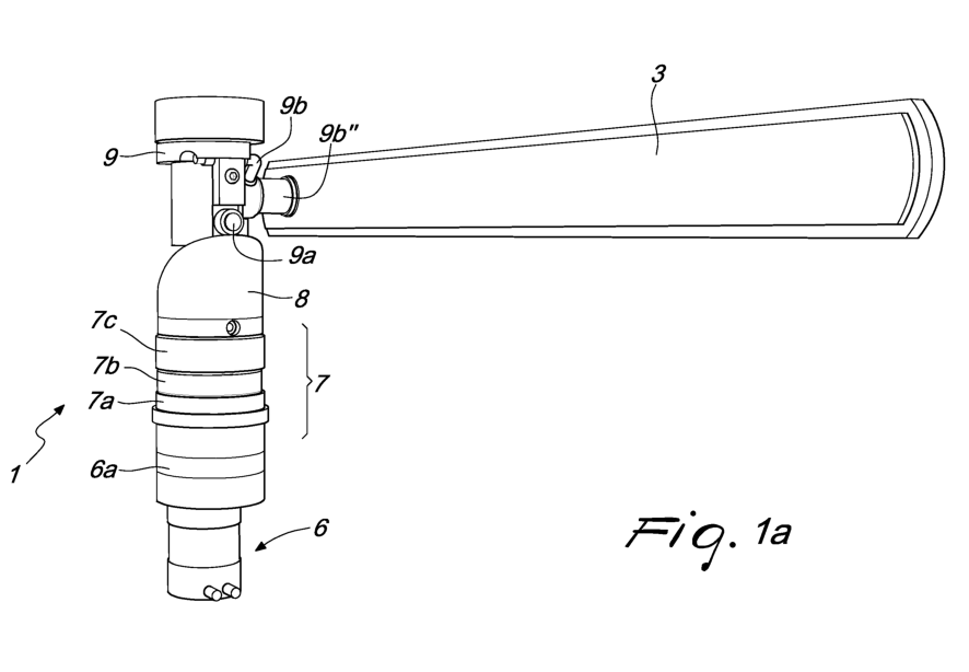
Figure 1a is a front view of some components of the said turnstile door
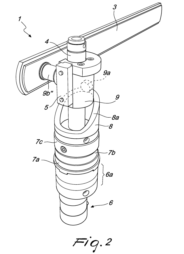
Figure 2 is a perspective view of the said turnstile door of Figure 1a;
Figure 3 is a view of a first detail of the said turnstile door
Figures 4-6 are additional views of other details of the said turnstile door
Figures 7a-7d are views of various configurations assumed by the said turnstile
An exemplifying architecture of the turnstile is shown in Figure 1.
Figure 1 shows a turnstile, designated generally by the reference numeral 1. The turnstile door 1 comprises an enclosure 2, a bar 3 and a plurality of components arranged inside the enclosure – including a motor 6, a reduction unit 7, a cam 8 and a slider 9 – which are shown in dashed lines. The enclosure 2 is preferably divided into two distinct components, in particular a first component 2a, which is integral with a fixed surface, for example the floor or the ground on which the turnstile 1 is accommodated, and a second component 2b, which can rotate.Preferably, the enclosure 2 is shaped like a tube and the two components 2a and 2b are conveniently provided as two steel tubes having an equal circular cross-section, which can be superimposed preferably in such a manner that the respective axes of longitudinal extension coincide. In one embodiment, the component 2b is associated rotatably with the first component 2a so as to rotate about an axis which coincides with the axis of longitudinal extension of the first component 2a. The enclosure 2 is hollow, i.e., it has a cavity that is adapted to contain various components and a supporting pole 4, which is preferably fixed and is integral with the first component 2a and is extended parallel to the longitudinal extension of the enclosure 2.
The first component 2a and the pole 4 are configured so as to be integral with the resting surface on which the turnstile door 1 is arranged. In one embodiment, the supporting pole 4 is substantially concentric with the enclosure 2.
The supporting pole 4 is preferably cylindrical and hollow but it should be understood that its shape can also be different, provided that it is suitable to support the various internal components of the turnstile 1.
For example, the supporting pole 4 can be replaced with a series of shafts which are mutually connected concentrically or in an axially offset manner.
The bar 3 for obstructing an access is of a known type and is configured so as to block a passage controlled by the turnstile door 1. The bar 3 is capable of rotating through 360° about the pole 4 or in any case about an axis that is parallel to the pole 4. Furthermore, the bar 3 is of the lowerable type and is adapted to pass reversibly from a first position (which is horizontal, i.e., parallel to the ground), in which it is substantially perpendicular to the pole 4 so as to block an access, and a second position (vertical, i.e., perpendicular to the ground), in which it is arranged parallel to the pole 4 so that it does not hinder access. The bar 3 has an angle, termed lowering angle, which is associated therewith and which in the first position is substantially right and in the second position is zero. Preferably, the breadth of the lowering angle is equal to: a) substantially 90° when the rotation angle is substantially 0°, so that the bar 3 is perpendicular to the pole and prevents access; b) substantially 0° when the rotation angle is equal to substantially 90°, so that the bar is parallel to the pole 4 and is arranged on an opposite side with respect to the side of the access and does not hinder access; c) substantially 90° when the rotation angle is equal to substantially 360°, i.e., when the bar 3 has performed a full rotation about an axis that is parallel to the fixed pole 4.
With reference to Figure 1a, the internal components of the turnstile door 1 are described.
The motor 6 is adapted to be arranged preferably inside the first component 2a and is conveniently supported by supporting means, which can include the supporting pole 4. Preferably, the motor 6 is of the brushless servomotor type. Conveniently, the motor 6 transmits the rotary motion to a set of gears 6a (first reduction stage), which in the preferred embodiment comprise a ring gear and a pinion.
The set of gears 6a has a reduction ratio, preferably 1:3, associated therewith. In Figure 1a, the various components 6, 6a are shown as being contained in respective containers. The motor 6 is adapted to generate a motion which, by means of the reduction unit 7, turns the second component 2b.
The reduction unit 7 is a device that comprises a series of gears (second reduction stage), which are assigned to reducing the speed and in particular the rotation speed transmitted by the gears 6a associated with the motor 6. In Figure 1a, the component 7 is shown as contained within a container. In the preferred embodiment, the reduction unit 7 is of the cycloidal type (or “cyclo”, which is different from the planetary epicyclic type) and comprises a ring gear with pins 7a, a male cycloid gear 7b and a ring gear 7c, termed output ring gear. Preferably, the reduction unit 7 has a reduction ratio of 1:21.The output ring gear 7c comprises a screw retention element that is adapted to engage the second component 2b so as to make it rotate, transmitting thereto the motion generated by the motor and subsequently submitted to the two stages (first and second) for reduction.
The cam 8 is fixed integrally to the pole 4 and is adapted to be arranged between the reduction unit 7 and the slider 9. Specifically, the cam 8 lies on the reduction unit 7 and has, on a side that lies opposite the one where the reduction unit 7 is located, a contact surface for the slider 9. Such surface forms a path 8a for a follower 9a that is associated with the slider 9. The path 8a, for example, is an ellipse, arranged obliquely with respect to the pole 4 and in any case comprises at least two points arranged at different heights. In one embodiment, the cam 8 has substantially the shape of a frustum, preferably hollow, with a substantially elliptical cross-section, in which the edge of the cross-section defines the contact surface and therefore the path for the follower 9a. In one embodiment, the actuation of the bar 3 is performed also by means of the cam 8 actuated by the same motor 6 that performs the rotation.
The slider 9 is a device capable of sliding along the hollow pole 4 and of rotating about it. In particular, the slider 9 has an annular cross-section within which the pole 4 slides. The slider 9 is further provided with the follower 9a, which is adapted to slide along a contact surface of the cam 8. Preferably, the follower 9a of the slider 9 is provided by means of a cam follower roller or bearing. Conveniently, the slider 9 can slide vertically along the pole 4 as a function of the position of the follower 9a on the path 8a of the cam 8 and optionally of the rotation of the cam 8.
Furthermore, the slider 9 can rotate about the pole 4. In particular, the slider 9 is configured to be engaged by the sliding block 5: since the sliding block 5 is integral with the second component 2b and the slider 9 is connected to the bar 3, the rotation of the component 2a accordingly causes the rotation, termed first rotation, of the bar 3 about the pole 4. In other words, the component 2b of the enclosure is moved by the output of the element 7c of the reduction unit 7. The element 2b is connected to the sliding block 5, which in turn engages the slider 9.
Therefore, the rotation of the slider 9 supported by the sliding block 5 causes the rotation of the bar 3 about the longitudinal axis of the pole 4.
The slider 9 is provided furthermore with a mechanism 9b adapted to impart a rotation, termed second rotation, to the bar 3 along an axis that is substantially perpendicular to the pole 4 so as to allow its lowering. In the preferred embodiment, the mechanism 9b is provided as a right-angled crank, which, as a function of the position of the follower 9a, lifts or lowers, i.e., rotates along an axis that is perpendicular to the pole 4, the bar 3. For example, according to one embodiment, if the follower 9a is located at the highest point of the cam 8, then the mechanism 9b acts on the bar 3 so that it is in a horizontal position (parallel to the resting surface of the turnstile 1), while when it is in the lowest point of the path the bar 3 is in a vertical position (at right angles to the resting surface of the turnstile 1). The mechanism 9b can be provided also in a different manner, for example by means of a device of the Uniball type. Therefore, the movement of the slider 9 causes the lifting and lowering of the bar 3.
Figure 2 is a perspective view of the turnstile door 1 in which the external enclosure 2 is not shown.
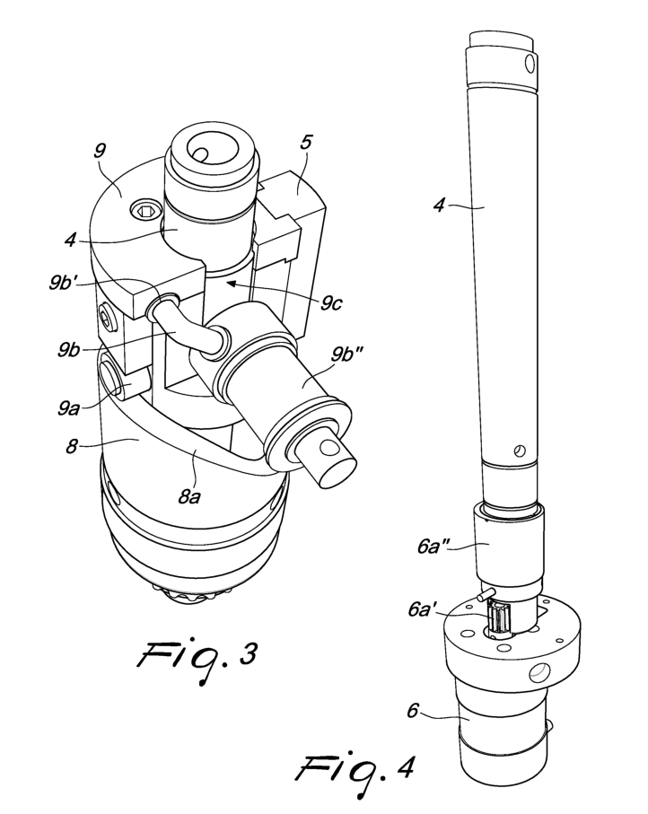
Figure 3 is a perspective view of the upper part of the turnstile door 1, which is preferably adapted to be contained in the component 2b. The configuration of the components shown in Figure 3 preferably corresponds to the configuration in which the bar 3 is horizontal and prevents user passage. In particular, the roller 9a is in the highest position with respect to the cam 8 and the crank 9b keeps the arm 9b” that supports the bar 3 in such a position that the bar 3 is in the horizontal configuration. The rotation of the enclosure or jacket 2b causes the movement of the roller 9a along the path 8a of the cam 8: accordingly, the slider 9 slides along the pole 4. During sliding, the crank 9b, which is pivoted in the point 9b’, rotates the arm 9b” along a seat 9c obtained from the slider 9. Conveniently, therefore, the crank 9b and the arm 9b” can provide a kinematic system of the rod-and-crank type. The seat 9c can be provided as a discontinuity of the slider 9. When the roller 9a reaches the lowest point of the path 8a (i.e., it has rotated through approximately 90°, moving to a low point of the path), the crank 9b acts on the bar 3, lowering it completely. A new rotation through 270° turns the bar 3 to the initial position.
Figure 4 shows in greater detail some elements of Figure 1, i.e., the brushless servomotor 6, the pinion 6a’ of the first reduction stage, the eccentric shaft of the second reduction stage 6a” and the supporting pole 4. In particular, the first reduction stage comprises a hollow gear which turns an eccentric shaft of the second reduction stage. The first reduction stage can be contained in a cup-shaped support.
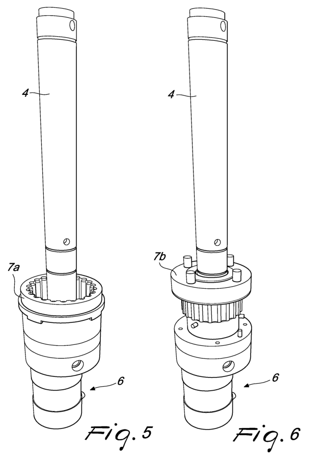
Figure 5 shows with greater detail some elements of Figure 1 and in particular the stator of the second reduction stage and the coupling on the external pole connected to the footing.
Figure 6 shows with greater detail the cycloidal gear 7b of the second reduction stage 7. For the sake of simplicity in description, the figure does not show the component 7c, which is to be understood as being part of the lower part of the turnstile 1. The component 7c is provided with holes that can be engaged with play on pins (four are shown in a non-limiting manner in the figure) of the component 7b. The second stage can comprise an eccentric shaft that is coupled on a fixed “pin wheel” which, for each turn of the eccentric shaft, skips by one pin, reducing the rotation speed by preferably 1:21.
How to operate the new turnstile door for access control
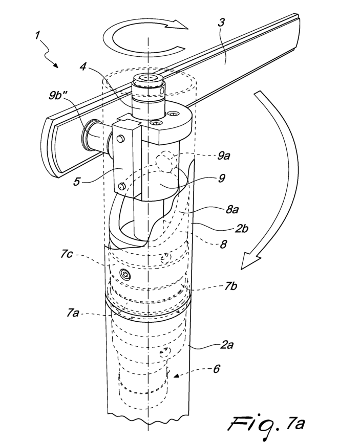
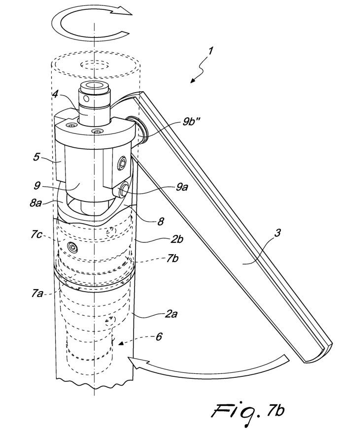
The turnstile 1 is an initial position for blocking access, in which the bar 3 is parallel to the resting surface of the turnstile 1, i.e., in a horizontal position, assuming the configuration shown in Figure 7a. It is assumed that the passage controlled by the turnstile 1 is the one arranged on the right side of the pole 4 as shown in Figure 7a and that the user accesses from the left side of Figure 7a, in which the bar 3 is arranged.
As a consequence of a given command (for example received by an external control unit or obtained on the basis of a reading of a badge for access control), the bar 3 that is in the initial position begins to move. In particular, since the slider 9 rotates about the pole 4, the bar 3 also rotates about the pole 4. Additionally, however, the slider 9 slides along the pole 4 due to the path followed by the roller 9a on the edge 8a’ of the cam 8. As a consequence of the variation of the position of the slider 9, the mechanism 9b moves the bar 3, making it gradually lower or collapse until it assumes the vertical position. In particular, Figure 7b shows one of the intermediate positioning steps, i.e., a configuration in which the bar is inclined with respect to the pole by a lowering angle that is preferably comprised between 0° and 90°.
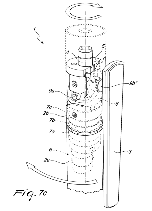
Figure 7c shows the configuration assumed by the bar 3 as a consequence of a rotation through 180° with respect to the initial position: the bar 3 is displaced on the opposite side with respect to the one where the bar 3 was in the initial position: the bar 3 is completely lowered and has assumed a vertical position. At this point the bar 3 is on the opposite side with respect to the user, does not hinder passage but advantageously does not cause space occupation since it is against the turnstile
Advantageously, the turnstile 1 can therefore be installed next to a wall or even next to other turnstiles 1. Once the bar 3 has been lowered, the user can thus cross the turnstile.
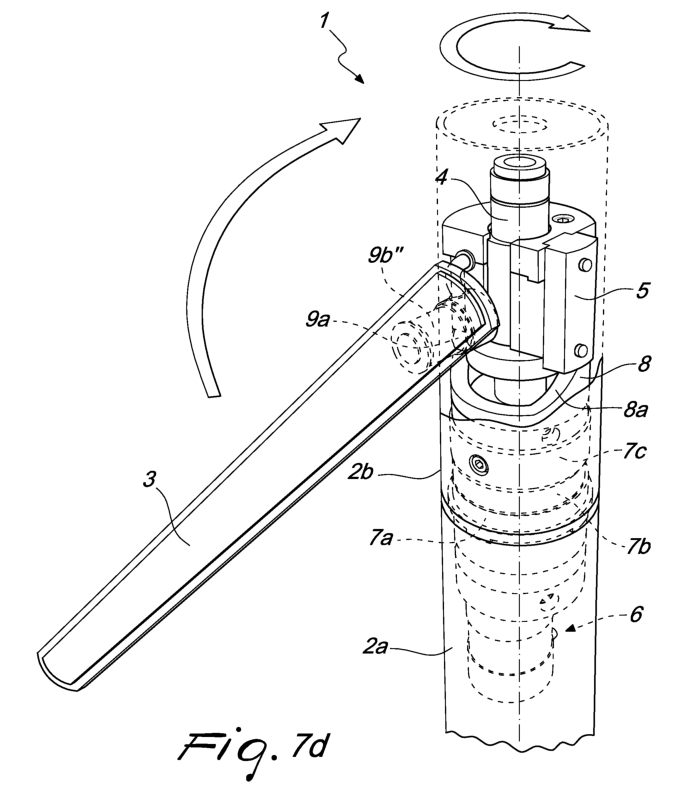
The bar 3, therefore, continues to move gradually, rotating and assuming the intermediate configuration shown in Figure 7d, continuing its motion until it assumes again the initial configuration shown in Figure 7a. Upon completion of the rotation, the follower 9a is located in the initial position again and accordingly the slider 9 also is in the initial position, preferably at a maximum height on the path 8a, which entails repositioning the bar 3 in the initial locking portion, i.e., parallel to the ground. The bar 3 then closes directly behind the user that has passed, rendering advantageously unnecessary a photocell for detecting the presence or passage of the user. Preferably, the turnstile 1 is provided furthermore with at least one sensor that detects the correct placement of the bar 3 and in particular the correct stop position of the bar 3.
Preferably, the turnstile 1 is provided with means for processing a command, which cause the movement of the bar 3. The command might be received from an external control unit and for example might consist in making the turnstile 1 assume, in an emergency situation, the configuration for free passage of users (bar 3 lowered, perpendicular to the ground).
The command can also be obtained, typically in conditions for ordinary use of the turnstile 1, on the basis of a reading of a badge for access control on the part of a reader connected to the processing means.
It has thus been shown that the method and the system described achieve the intended aim and objects. In particular, it has been shown that the system thus conceived allows to overcome the qualitative limitations of the background art. In particular, the turnstile 1 according to the invention allows to achieve the advantages of conventional turnstiles without being affected by their defects. In fact, advantageously the bar 3 follows a path that is entirely similar to the cone traced by a tripod turnstile, without however causing a space occupation since it does not protrude on the opposite side with respect to the side for the passage of the user.
Furthermore, advantageously it is possible to deactivate the turnstile 1 in case of emergency, stopping the bar 3 in a vertical position. The turnstile ensures reversibility, which is provided by the fact that the turnstile can operate identically for clockwise or counterclockwise rotations: in any case, the bar 3 lowers and rises again behind the user.
Clearly, numerous modifications are evident and can be performed promptly by the person skilled in the art without abandoning the protective scope of the appended claims. For example, nothing forbids the use of a photocell if deemed appropriate. Moreover, it is possible to use a capacitive sensor within the body of the bar in order to detect the mass of the human body of the user who is crossing the turnstile.
Therefore, the scope of the protection of the claims must not be limited by the illustrations or preferred embodiments shown in the description by way of example.
Where technical features mentioned in any claim are followed by reference signs, those reference signs have been included for the sole purpose of increasing the intelligibility of the claims and accordingly such reference signs do not have any limiting effect on the interpretation of each element identified by way of example by such reference signs.
Claims
1. A secure turnstile (1) for access control, comprising:
– a supporting pole (4);
– a motor (6);
– an access obstruction bar (3) connected to said pole (4);
said access obstruction bar (3) being adapted to rotate about a substantially parallel axis and a substantially perpendicular axis with respect to the longitudinal axis of the pole (4) so as to pass from a horizontal position, in which it is substantially perpendicular to said pole (4), to one or more intermediate positions, in which it is inclined with respect to said pole (4), and to a vertical position, in which it is substantially parallel to said pole (4), characterized in that it further comprises:
– an enclosure (2) having a first component (2a) that is integral with a fixed surface and a second component (2a) that can rotate; said enclosure (2) having a cavity adapted to contain said supporting pole (4), which is integral with said first component (2a), said pole (4) extending parallel to the longitudinal extension of the enclosure (2);
– said motor (6) being adapted to be contained in said enclosure (2) and to turn said second component (2b) by means of a reduction unit (7);
– a slider (9) associated rotatably and slidingly with said pole (4), said slider (9) being moreover connected to said bar (3) and to a sliding block (5) that is integral with said rotatable component (2b);
– a cam (8) which is integral with said pole (4) and is adapted to be arranged between said reduction unit (7) and said slider (9); said slider (9) being provided with a follower (9a) adapted to slide along a contact surface of said cam (8), said contact surface forming a path (8a) having at least two points arranged at different heights; said bar (3) being adapted to rotate about said substantially parallel axis and said substantially perpendicular axis with respect to the longitudinal axis of the pole (4) depending on the position of said follower (9a) on said path (8a).
2. The turnstile solution according to claim 1, characterized in that said reduction unit (7) is of the cycloidal type and comprises a ring gear (7a) with pins, a male cycloidal gear (7b) and a second ring gear (7c).
3. The turnstile according to claim 2, characterized in that said second ring gear (7c) comprises a screw-type retention element adapted to engage said second component (2b) so as to make it rotate by transmitting thereto the motion generated by said motor (6).
4. The entrance gateturnstile according to one or more of the preceding claims, characterized in that said slider (9) is connected to said bar (3) by means of a mechanism (9b) connected to an arm (9b’); said arm (9b’) being adapted to support said bar (3) and to move within a seat (9c) formed in said slider (9); said mechanism (9b) and said arm (9b’) being designed to rotate said bar (3) about an axis that is substantially perpendicular to the axis of said pole (4) depending on said position of said follower (9a) on said path (8a).
5. The path turnstile according to claim 4, characterized in that said mechanism (9b) comprises a right-angled crank or a device of the Uniball type; said follower (9a) of said slider (9) comprising a roller or a cam follower bearing.
6. The automated turnstile according to one or more of the preceding claims, characterized in that said motor (6) actuates reduction gears (6a) adapted to mesh with said reduction unit (7).
7. The turnstile entry system according to claim 6, characterized in that said reduction gears (6a) have a 1:3 reduction ratio; said reduction unit (7) having preferably a 1:21 reduction ratio.
8. The turnstile entrance gate according to one or more of the preceding claims,characterized in that said cam (8) is substantially frustum-shaped, preferably hollow, with an elliptical cross-section, the edge of said elliptical cross-section forming said contact surface for said follower (9a).
9. The turnstile according to one or more of the preceding claims, characterized in that said bar (3) is capable of performing a 360° rotation about the longitudinal axis of said pole (4); said bar (3) being of the lowerable type and being adapted to pass reversiblyfrom a first position, in which said bar (3) is substantially perpendicular to said pole (4) so as to block an access, and a second position, in which said bar (3) is substantially arranged parallel to said pole (4) so as not to hinder access.
10. The turn style gates according to one or more of the preceding claims, characterized in that said bar (3) has an associated lowering angle, the breadth of which is a function of the rotation angle of the bar (3) about an axis that is parallel to said pole (4).
11. The optical barrier turnstile according to claim 10, characterized in that said lowering angle is equal to:a) substantially 90° when said rotation angle is substantially 0°; b) substantially 0° when said rotation angle is equal to or greater than 90°; c) substantially 90° when said rotation angle is equal to substantially 360°.
12. The security optical turnstile according to one or more of the preceding claims, characterized in that it comprises means for processing a command for causing the motion of said bar (3), said command being received by an external control unit or obtained on the basis of a reading of a badge for access control.


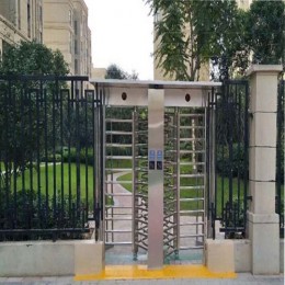


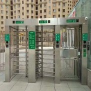
 Double Lane Full Height Turnstile Gate for Residential Area
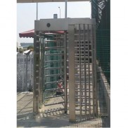
 Dual Lane Tandem Full Height Turnstile Gate for Industry Park
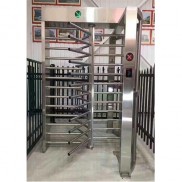 Single Full Height Security Turnstile for Office Buildings
 Motorised Double Full-Height Turnstile for Office Buildings
Please leave a message if you are interested in this model