Access turnstile for supermarkets and similar places
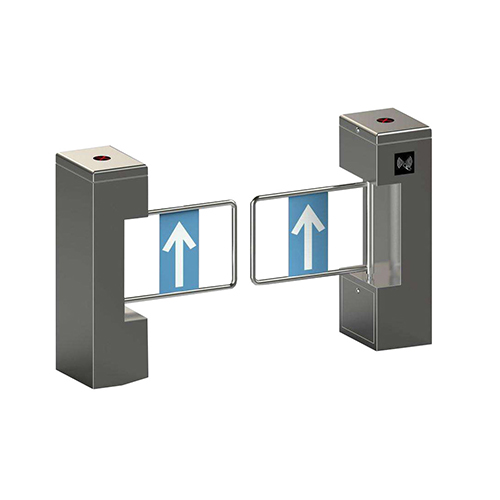
What is an acess turnstile?
Access turrnstile is generally used in supermarkets or similar establishments, comprising a vertical shaft around the axis of which at least one support part is capable of rotating and to which is connected by means of a plastic locking device a transverse bar forming the opening of modern security gate, the support piece and the transverse bar remaining, in normal service, integral with one of the other and pivoting from a closing position to an opening position of the turnstile door, the plastic locking device being capable of allowing the crossbar to pivot relative to the support part so as to take an opening position opposite to the normal open position.
In turnstile barrier, the crossbar is brought into its normal open position by a pushing force and elastic means are necessary to return this crossbar to its closed position. Its crossbar can be brought into its normal opening position without having to exert a lifting force. pushed and is returned to its closed position without requiring the presence of plastic means in which the device Plastic lock is of relatively simple construction.
The vertical shaft, on which said support piece is fixed, is constituted by the shaft of a electric motor actuated by signals from a passage detection system and in that the crossbar is maintained on the support piece laterally by two cylindrical rods fixed on the support piece and vertically by a bolt fixed in the transverse bar, passing through the support piece and comprising between the support piece and its head a spring, said bolt, spring and stems forming said plastic locking device.
Thus the crossbar is automatically brought into its normal open position or returned to its closed position, the elastic locking device also being of extremely simple construction.
How does an access turnstile works?
In order to better understand the object, it will be described in more detail below while referring to the drawings. annexed with a practical, but non-restrictive, form of execution, in which:
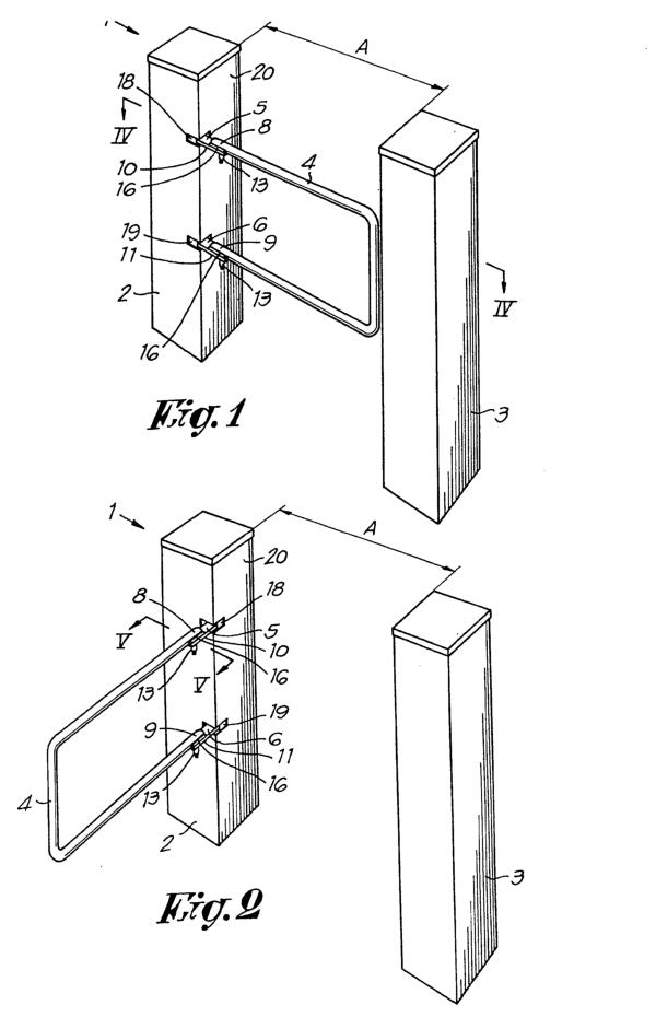
Figure 1 is a perspective view of the access turnstile in the closed position;
Figure 2 is a perspective view of the access turnstile in the conventional open position;
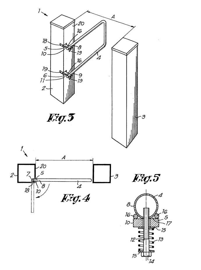
Figure 3 is a perspective view of a access gate in the open position in the opposite direction;
Figure 4 represents a view along line IV—VI in Figure 1: and
Figure 5 shows, on an enlarged scale, a section along the line V—V in Figure 2.
Figure 1, the entrance gate 7 is shown in the closed position, that is to say blocking the passage A delimited by the vertical limit plane of the console 2 and the vertical limit plane of a second console, a pillar or of a wall 3.
The turnstile security barrier consists substantially of an opening, preferably made by a transverse bar4 bent in the shape of a U, supported by the console 2 via support levers 5, 6. Inside the console 2, the support levers 5,6 are fixed to a shaft vertical7 controlled by an electric motor not shown. The electric motor is itself actuated by a passage detection system not shown but well known.
The free ends 8 and 9 of the opening 4 are fixed on the protuberant ends 0, 11 of the support levers 5,6 by means of bolts 72 (figure 5). Springs II are provided between the heads 14 of the bolts 72 and the lower faces of the support levers 5,6 so as to allow adjustment of the pressure with which the free ends 8, 9 of the opening 4 are held on the ends 10, 11 support levers 5, 6. On either side of the springs l3 are provided washers 15.
The ends 10, 11 of the support levers 5,6 are provided at their longitudinal edges with two mutually cylindrical rods f6 parallel, welded to the upper faces of said levers 5,6 and extending longitudinally relative to them. The rods 16 are spaced from each other at a distance slightly less than the diameter of the bar 4, the diameter of said rods 16 being considerable – lower than the latter.
When the gate is in the normal closed position (figure 1), the free ends 8, 9 of the bar4 rest in the housings f7 formed by the rods 16 and the upper faces of the levers 5, 6. Thus, and by force exerted by the springs 13, the opening 4 normally remains held in the extension of the levers 5, 6.
When a person passes through the known detection device, not shown, it turns the vertical shaft 7′ and, therefore, the levers of support 5, 6. Thus, the opening 4 is forced to follow this movement to reach the opening position as shown in Figure 2.
It will be noted that, according to a particular characteristic, the levers 5, 6 are able to move in rectangular windows 18, 19 so that the passageA is completely clear, no part of the gatef and more particularment of the opening 4 not projecting from the faces 20 of the console 2 facing said passage.
After having respected a necessary delay to let the person in question pass, the gate turnstile closes automatically and returns to the position shown in Figure 1
When the optical barrier turnstile is in the closed position, the opening 4 can, in the event of a fire for example, be pushed back manually towards the rear, through the application of a certain minimum force, so that the access gate 7 is in the position as shown in Figure 3. The above-mentioned minimum force is the force at overcome on the one hand to lift the free ends 8, 9 of the opening 4 of the housings 17 against the force exerted by the springs 13 and on the other hand to overcome the friction between the respective parts. It will be noted that in this case an evacuation passage of width substantially equal to that of passage A can be made available to the public for evacuation.
It is clear from Figure 4 that the conventional passage A can be used over its entire width, while in known mini turnstile, the width of the passage A is always reduced by the thickness of the opening. Indeed, in the open position, the known revolving turnstiles present the danger of the user colliding with the bend of the opening protruding from the face of the console facing the passage. Furthermore, of by the monolithic construction of the opening connected directly to the control shaft, the legally obligatory unlocking device is provided at the height of the control shaft itself, which has the consequence that if necessary the gate does not can be pushed completely backwards since it is held back a certain moment through the rear end of the windows provided in the face of the console facing the passage. Thus, with the known bi-directional turnstiles, we do not can obtain only a partially open passage which is clearly insufficient to guarantee rapid evacuation of the establishment.
The pedestrian barrier gate also has the advantage that, due to its original design, the opening 4 cannot be forced or twisted and that, consequently, the electric motor runs no risk of overloading, which is not not the case in the gates known.
It is obvious that many modifications described above as an illustrative but non-limiting example and that the shapes and dimensions of individual parts can be chosen in proportion to local requirements. Thus, the consoles do not necessarily have to have a square cross-section shape, but they can just as easily be made in a cylindrical shape by example.
Claim
Access turnstile is generally used in supermarkets or similar enterprises, comprising a vertical spindle (7) around whose axis at least one support piece (5) can swivel and to which is connected a cross-bar (4) acting as the opening part of the access door, by means of an elastic locking device (12-17), the support piece (5) and cross-bar (4) staying firmly attached to one another in normal operation, swivelling jointly from a closed position to an open position of the access door, whereas the elastic locking device (12—17) may enable the cross-bar (4) to turn with respect to the support piece (5), so as to reach an open position opposite to the normal open position, featuring that the vertical spindle (7)on which said support piece is fastened, consists of the shaft of an electric motor controlled by signals proceeding froma passage detecting system and that the cross-bar (4) is secured sideways to the support piece (5) by two cylindrical pins (16) fastened to the support piece and vertically bya bolt (12) fitted in the crossbar (4) and passing through the support piece (5), this bolt holding between the support piece (5) and its head (14)a spring (13), whereas the said bolt, spring and pins compose the said elastic locking device.
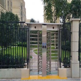
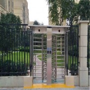 Double Lane Full Height Turnstile Gate for Residential Area
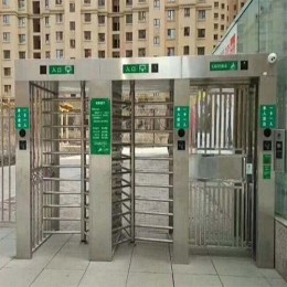
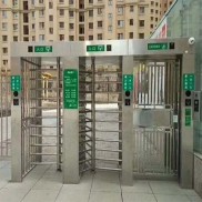 Dual Lane Tandem Full Height Turnstile Gate for Industry Park
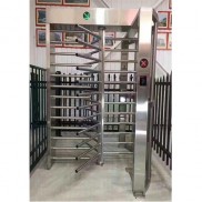 Single Full Height Security Turnstile for Office Buildings
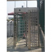 Motorised Double Full-Height Turnstile for Office Buildings




Please leave a message if you are interested in this model